Dear Bobot, could you tell us a little more about impulses?
It's good that you asked, my friend Bibot. Since pulses are the main carriers of information in digital electronics, it is therefore very important to know the different characteristics of pulses. Let's start, perhaps, with a single impulse.
An electrical impulse is a surge of voltage or current in a certain and finite period of time.
A pulse always has a beginning (rising edge) and an end (falling edge).
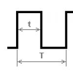
You probably already know that in digital electronics all signals can be represented by just two voltage levels: “logical one” and “logical zero”. These are just conventional voltage values. A “logical one” is assigned a high voltage level, usually about 2-3 volts, while a “logical zero” is considered a voltage close to zero. Digital pulses are graphically represented as rectangular or trapezoidal in shape:
The main quantity of a single pulse is its length. The pulse length is the length of time during which the logic level in question has one stable state. In the figure, the Latin letter t marks the length of the high-level pulse, that is, logical “1”. Pulse length is measured in seconds, but more commonly in milliseconds (ms), microseconds (μs), and even nanoseconds (ns). One nanosecond is a very short period of time!
Remember: 1 ms = 0.001 sec.
1 µs = 0.000001 sec
1 ns = 0.000000001 sec
English abbreviations are also used: ms - millisecond, μs - microsecond, ns - nanosecond.
In one nanosecond I won’t even have time to make a sound!
Tell me, Bobot, what will happen if there are a lot of impulses?
Good question, Beebot! The more impulses, the more information they can convey. Many impulses have many characteristics. The simplest is the pulse repetition rate.
The pulse repetition rate is the number of complete pulses per unit time. It is customary to take one second per unit of time. The unit of frequency is the hertz, named after the German physicist Heinrich Hertz. One hertz is the recording of one complete pulse in one second. If a thousand vibrations occur per second, it will be 1000 hertz, or abbreviated 1000 Hz, which is equal to 1 kilohertz, 1 kHz. You can also find the English abbreviation: Hz - Hz. The frequency is indicated by the letter F.
There are several more characteristics that appear only with the participation of two or more impulses. One of these important parameters of the pulse sequence is the period.
The pulse period is the time interval between two characteristic points of two adjacent pulses. Typically, the period is measured between two rises or two falls of adjacent pulses and is denoted by a capital Latin letter T.

The pulse repetition period is directly related to the frequency of the pulse sequence, and it can be calculated using the formula: T=1/F
If the pulse length t exactly equal to half the period T, then such a signal is often called " meander".
The duty cycle of pulses is the ratio of the pulse repetition period to their duration and is denoted by the letter S: S=T/t Duty factor is a dimensionless quantity and has no units of measurement, but can be expressed as a percentage. The term Duty cycle is often found in English texts; this is the so-called duty cycle.
The duty cycle D is the reciprocal of the duty cycle. The fill factor is usually expressed as a percentage and is calculated by the formula: D=1/S
Dear Bobot, simple impulses have so many different and interesting things! But little by little I'm starting to get confused.
My friend, Bibot, you noticed correctly, impulses are not so simple! But there is just a little left.
If you listened to me carefully, then you might have noticed that if you increase or decrease the pulse length and at the same time decrease or increase the pause between pulses by the same amount, then the pulse repetition period and frequency will remain unchanged! This is a very important fact that we will need more than once in the future.
But now I still want to add other ways of transmitting information using impulses.
For example, several impulses can be combined into groups. Such groups with pauses of a certain length between them are called bursts or packets. By generating a different number of pulses in a group and varying it, you can also transmit any information.

To transmit information in digital electronics (also called discrete electronics), two or more conductors or channels with different pulse signals can be used. In this case, information is transmitted taking into account certain rules. This method allows you to significantly increase the speed of information transfer or adds the ability to control the flow of information between different circuits.
The listed possibilities for transmitting information using impulses can be used either on their own separately or in combination with each other.
There are also many standards for transmitting information using pulses, for example I2C, SPI, CAN, USB, LPT.
Previously, to power devices, they used a circuit with a step-down (or step-up, or multi-winding) transformer, a diode bridge, and a filter to smooth out ripples. For stabilization, linear circuits using parametric or integrated stabilizers were used. The main disadvantage was the low efficiency and large weight and dimensions of powerful power supplies.
All modern household electrical appliances use switching power supplies (UPS, IPS - the same thing). Most of these power supplies use a PWM controller as the main control element. In this article we will look at its structure and purpose.
Definition and Main Benefits
A PWM controller is a device that contains a number of circuit solutions for controlling power switches. In this case, control occurs on the basis of information received through feedback circuits for current or voltage - this is necessary to stabilize the output parameters.
Sometimes PWM pulse generators are called PWM controllers, but they do not have the ability to connect feedback circuits, and they are more suitable for voltage regulators than for providing stable power to devices. However, in the literature and Internet portals you can often find names like “PWM controller, on NE555” or “... on Arduino” - this is not entirely true for the above reasons, they can only be used to regulate output parameters, but not to stabilize them.

The abbreviation “PWM” stands for pulse-width modulation - this is one of the methods of modulating a signal not due to the output voltage, but precisely by changing the pulse width. As a result, a simulated signal is formed by integrating pulses using C- or LC-circuits, in other words, by smoothing.
Conclusion: A PWM controller is a device that controls a PWM signal.
Main Features
For a PWM signal, two main characteristics can be distinguished:
1. Pulse frequency - the operating frequency of the converter depends on this. Typical frequencies are above 20 kHz, in fact 40-100 kHz.
2. Duty factor and duty cycle. These are two adjacent quantities characterizing the same thing. The duty cycle can be denoted by the letter S, and the duty cycle by D.
where T is the signal period,
The portion of time from the period when a control signal is generated at the controller output is always less than 1. The duty cycle is always greater than 1. At a frequency of 100 kHz, the signal period is 10 μs, and the switch is open for 2.5 μs, then the duty cycle is 0.25, as a percentage - 25 %, and the duty cycle is 4.

It is also important to consider the internal design and purpose of the number of keys managed.
Differences from linear loss schemes
As already mentioned, the advantage over linear circuits is the high efficiency (more than 80, and currently 90%). This is due to the following:
Let's say the smoothed voltage after the diode bridge is 15V, the load current is 1A. You need to get a stabilized 12V power supply. In fact, a linear stabilizer is a resistance that changes its value depending on the input voltage to obtain a nominal output - with small deviations (fractions of volts) when the input changes (units and tens of volts).
As is known, resistors release thermal energy when electric current flows through them. The same process occurs on linear stabilizers. The allocated power will be equal to:
Ploss=(Uin-Uout)*I
Since in the considered example the load current is 1A, the input voltage is 15V, and the output voltage is 12V, we will calculate the losses and efficiency of the linear stabilizer (KRENK or type L7812):
Ploss=(15V-12V)*1A = 3V*1A = 3W
Then the efficiency is equal to:
n=Puseful/Pconsumed
n=((12V*1A)/(15V*1A))*100%=(12W/15W)*100%=80%
The main feature of PWM is that the power element, let it be a MOSFET, is either completely open or completely closed and no current flows through it. Therefore, efficiency losses are due only to conductivity losses
And switching losses. This is a topic for a separate article, so we will not dwell on this issue. Also, power supply losses occur (input and output, if the power supply is network-powered), as well as on conductors, passive filter elements, etc.
General structure
Let's consider the general structure of an abstract PWM controller. I used the word “abstract” because, in general, they are all similar, but their functionality may still differ within certain limits, and the structure and conclusions will differ accordingly.
Inside the PWM controller, like any other IC, there is a semiconductor crystal on which a complex circuit is located. The controller includes the following functional units:
1. Pulse generator.
2. Reference voltage source. (ION)
3. Circuits for processing the feedback signal (OS): error amplifier, comparator.
4. Pulse generator controls built-in transistors, which are designed to control a power key or keys.
The number of power switches that a PWM controller can control depends on its purpose. The simplest flyback converters in their circuit contain 1 power switch, half-bridge circuits (push-pull) - 2 switches, bridge circuits - 4.

The choice of PWM controller also depends on the type of key. To control a bipolar transistor, the main requirement is that the output control current of the PWM controller is not lower than the transistor current divided by H21e, in order to turn it on and off simply by sending pulses to the base. In this case, most controllers will do.
In the case of management, there are certain nuances. To quickly turn off, you need to discharge the gate capacitance. To do this, the gate output circuit is made of two keys - one of them is connected to the power supply with the IC pin and controls the gate (turns on the transistor), and the second is installed between the output and ground, when you need to turn off the power transistor - the first key closes, the second opens, closing shutter to the ground and discharges it.

Interesting:
Some PWM controllers for low-power power supplies (up to 50 W) do not use built-in or external power switches. Example - 5l0830R
Generally speaking, a PWM controller can be represented as a comparator, one input of which is supplied with a signal from the feedback circuit (FC), and a sawtooth changing signal is supplied to the second input. When the sawtooth signal reaches and exceeds the OS signal in magnitude, a pulse appears at the output of the comparator.
When the signals at the inputs change, the pulse width changes. Let's say that you connected a powerful consumer to the power supply, and the voltage at its output drops, then the OS voltage will also drop. Then, in most of the period, the sawtooth signal will exceed the feedback signal, and the pulse width will increase. All of the above is reflected to a certain extent in the graphs.


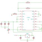
Functional diagram of a PWM controller using the TL494 as an example; we will look at it in more detail later. The purpose of the pins and individual nodes is described in the following subheading.

Pin assignment
PWM controllers are available in various packages. They can have from three to 16 or more conclusions. Accordingly, the flexibility of using the controller depends on the number of pins, or rather their purpose. For example, a popular microcircuit most often has 8 pins, and an even more iconic one has TL494- 16 or 24.
Therefore, let’s look at typical pin names and their purpose:
GND- the common terminal is connected to the minus of the circuit or to ground.
Uc(Vc)- power supply of the microcircuit.
Ucc (Vss, Vcc)- Output for power control. If the power sags, then there is a possibility that the power switches will not open completely, and because of this they will begin to heat up and burn out. The output is needed to disable the controller in such a situation.
OUT- as the name suggests, this is the output of the controller. The control PWM signal for power switches is output here. We mentioned above that converters of different topologies have different numbers of keys. The name of the pin may differ depending on this. For example, in half-bridge controllers it may be called HO and LO for the high and low switches, respectively. In this case, the output can be single-ended or push-pull (with one switch and two) - to control field-effect transistors (see explanation above). But the controller itself can be for single-cycle and push-pull circuits - with one and two output pins, respectively. This is important.
Vref- reference voltage, usually connected to ground through a small capacitor (units of microfarads).
ILIM- signal from the current sensor. Needed to limit the output current. Connects to feedback circuits.
ILIMREF- the trigger voltage of the ILIM leg is set on it
SS- a signal is generated for a soft start of the controller. Designed for smooth transition to nominal mode. A capacitor is installed between it and the common wire to ensure a smooth start.
RtCt- terminals for connecting a timing RC circuit, which determines the frequency of the PWM signal.
CLOCK- clock pulses to synchronize several PWM controllers with each other, then the RC circuit is connected only to the master controller, and the RT slaves with Vref, the CT slaves are connected to the common one.
RAMP is the comparison input. A sawtooth voltage is applied to it, for example from the Ct pin. When it exceeds the voltage value at the error amplification output, a shutdown pulse appears at OUT - the basis for PWM regulation.
INV and NONINV- these are the inverting and non-inverting inputs of the comparator on which the error amplifier is built. In simple words: the higher the voltage on INV, the longer the output pulses and vice versa. The signal from the voltage divider in the feedback circuit from the output is connected to it. Then the non-inverting input NONINV is connected to the common wire - GND.
EAOUT or Error Amplifier Output rus. Error amplifier output. Despite the fact that there are error amplifier inputs and with their help, in principle, you can adjust the output parameters, but the controller reacts to this rather slowly. As a result of a slow response, the circuit may become excited and fail. Therefore, signals are supplied from this pin through frequency-dependent circuits to the INV. This is also called error amplifier frequency correction.

Examples of real devices
To consolidate the information, let's look at a few examples of typical PWM controllers and their connection circuits. We will do this using the example of two microcircuits:
TL494 (its analogues: KA7500B, KR1114EU4, Sharp IR3M02, UA494, Fujitsu MB3759);
They are actively used. By the way, these power supplies have considerable power (100 W or more on the 12V bus). Often used as a donor for conversion into a laboratory power supply or a universal powerful charger, for example for car batteries.
TL494 - review
Let's start with the 494th chip. Its technical characteristics:


In this particular example, you can see most of the findings described above:
1. Non-inverting input of the first error comparator
2. Inverting input of the first error comparator
3. Feedback input
4. Dead time adjustment input
5. Terminal for connecting an external timing capacitor
6. Output for connecting a timing resistor
7. Common pin of the microcircuit, minus power supply
8. Collector terminal of the first output transistor
9. Emitter terminal of the first output transistor
10. Emitter terminal of the second output transistor
11. Collector terminal of the second output transistor
12. Supply voltage input
13. Input for selecting single-cycle or push-pull mode of operation of the microcircuit
14. Built-in 5 volt reference output
15. Inverting input of the second error comparator
16. Non-inverting input of the second error comparator
The figure below shows an example of a computer power supply based on this chip.

UC3843 - review
Another popular PWM is the 3843 chip - computer and other power supplies are also built on it. Its pinout is located lower, as you can see, it has only 8 pins, but it performs the same functions as the previous IC.
Interesting:
There are UC3843 in a 14-leg case, but they are much less common. Pay attention to the markings - additional pins are either duplicated or not used (NC).

Let's decipher the purpose of the conclusions:
1. Comparator (error amplifier) input.
2. Feedback voltage input. This voltage is compared with the reference voltage inside the IC.
3. Current sensor. It is connected to a resistor located between the power transistor and the common wire. Needed for overload protection.
4. Timing RC circuit. With its help, the operating frequency of the IC is set.
6. Exit. Control voltage. Connected to the gate of the transistor, here is a push-pull output stage to control a single-ended converter (one transistor), which can be seen in the figure below.
Buck, Boost and Buck-Boost types.
Perhaps one of the most successful examples will be the widespread LM2596 microcircuit, on the basis of which you can find a lot of converters on the market, as shown below.

Such a microcircuit contains all the technical solutions described above, and also instead of an output stage on low-power switches, it has a built-in power switch capable of withstanding a current of up to 3A. The internal structure of such a converter is shown below.

You can be sure that in essence there are no special differences from those discussed in it.
But here is an example on such a controller, as you can see, there is no power switch, but only a 5L0380R microcircuit with four pins. It follows that in certain tasks the complex circuitry and flexibility of the TL494 are simply not needed. This is true for low-power power supplies, where there are no special requirements for noise and interference, and the output ripple can be suppressed with an LC filter. This is a power supply for LED strips, laptops, DVD players, etc.

Conclusion
At the beginning of the article, it was said that a PWM controller is a device that models the average voltage value by changing the pulse width based on the signal from the feedback circuit. I note that the names and classifications of each author are often different; sometimes a PWM controller is called a simple PWM voltage regulator, and the family of electronic microcircuits described in this article is called “Integrated subsystem for pulse-stabilized converters.” The name does not change the essence, but disputes and misunderstandings arise.
Photo of the generator.

What can this generator do? Let's take a look at the parameters.
- Operating voltage: 3.3 - 30V;
- Generation frequency: 1Hz - 150KHz;
- Frequency generation accuracy: 2%;
- Load power: 5…30mA;
- The amplitude of the output signal is equal to the supply voltage;
- Ambient temperature: -20 … +70 °C.

Only 2 numbers of 3 digits each can be displayed. The bottom line displays the PWM duty cycle as a percentage, and the top line displays the frequency. The frequency is displayed according to the following rules:
- XXX, 1Hz step, range 1 – 999Hz;
- X.XX, step in 0.01 kHz, in the range 1.00 - 9.99 kHz;
- XX.X, step in 0.1 kHz; in the range 10.0 - 99.9 kHz;
- X.X.X, 1 kHz step; in the range 100 - 150 kHz.
The display is controlled by the HT1621B chip, the display is universal, it contains the symbols necessary to build a thermometer, hygrometer, voltmeter, ammeter and wattmeter, but in our case they are not used. The display has a bright blue backlight. By the way, I note that the display on my generator turned out to be shabby, as if it had been removed from somewhere.

The main chip of the generator is the STM8S003F3P6 microcontroller. And since this microcontroller has EEPROM memory, the settings are saved when turned off.
You can control the generator in two ways: buttons and via UART. Everything is clear with the buttons, one pair of buttons controls the frequency, the second the duty cycle. But with UART everything is much more interesting. Data exchange must occur with the following parameters:
- 9600 bps Data bits: 8
- Stop bit: 1
- Check digit: none
- Flow control: none
In order to set the generation frequency, you need to send the frequency as it is displayed on the display by adding the letter F in front of the frequency value. For example, to set the frequency to 100 Hz you need to send F100, for 105 kHz - F1.0.5, for 10.5 kHz - F10 .5 and so on.
To set the duty cycle, you need to send a three-digit duty cycle number by adding the letter D in front of it. For example, D050, D100, D001.
If a correct command is sent, the generator will respond DOWN, if an incorrect one - FALL. But there is one BUT, I was never able to configure work with the generator via UART.
I decided to test the generator using a logic analyzer. This is what happened.
Frequency 1 Hz, duty cycle 1%. As we can see, the error is still small.

Frequency 1 Hz, duty cycle 50%.

Frequency 1 Hz, duty cycle 99%.

Frequency 1 kHz, duty cycle 1%.

Frequency 1 kHz, duty cycle 50%.

Frequency 1 kHz, duty cycle 99%. Here we see that with the duty cycle set to 99%, the fill is actually 100%.

Frequency 1 kHz, duty cycle 91%. I began to reduce the duty cycle, and up to 92% the filling was 100%, and only at 91% the situation improved.

Frequency 50 kHz, duty cycle 1%. As you can see, it’s only 0.2% instead of 1%.

Frequency 50 kHz, duty cycle 50%. Here it differs by 1%.

Frequency 50 kHz, duty cycle 99%. And here again the deviation is -1%.

Frequency 100 kHz, duty cycle 1%. But there’s nothing here yet.

Frequency 100 kHz, duty cycle 2%. And at 2% the signal appears, but in fact the filling is 0.4%.

Frequency 100 kHz, duty cycle 50%. The deviation is almost -2%.

Frequency 100 kHz, duty cycle 99%. And here it’s almost -1%.

Frequency 150 kHz, duty cycle 1%. No signal again.

Frequency 150 Hz, duty cycle 3%. And the signal appears only at 3%, but the filling is 0.6%.

Frequency 150 kHz, duty cycle 50%. But in fact, the filling is 46.5%, a difference of -3.5%.

Frequency 150 kHz, duty cycle 99%. And there is an error, but only 1.5%.

The sample is quite rough, but the research is not over yet. I decided to measure the duty cycle at different duty cycles (5% steps) and at different frequencies (25000 Hz steps) and put them in a table.
The simplest generator of pulse-width signals.
The main purpose of the PWM Generator program is to generate pulse width modulation signals in real time. These tones are generated based on specified values of frequency (in Hertz), duty cycle - the ratio of time between low and high states of the signal (in percent), and amplitude - the level of the digital signal (in dBFS). All of the above parameters can be instantly changed during operation. The maximum possible signal level generated is 0 dBFS, and the highest frequency is half the sampling frequency. A whole menu of output characteristics is provided to configure the sound generation to the optimal level of quality. There is the ability to change the number and size of internal data buffers, sampling frequency and quantization.
The software can be used to create control tones for various electrical and electromechanical devices. In particular, the resulting PWM signal, taken from the output of the sound card of a personal computer and passed through a standard audio amplifier, is used to control motors, fans, and lighting devices.
PWM Generator supports working with several sound cards, and you can select the one that will be used to output the desired signal (by default, the program works with the output device specified in the Windows Control Panel). It is worth noting that the working PWM signal can be saved as a WAV file and later listened to using standard software. And if you regularly use certain tones, the PWM signal generator makes it possible to save (and load) them as presets. Additionally, several presets come with the app.
PWM Generator supports the option of synchronizing all running instances of the program, allowing you to generate several tones at once. It should be noted that the software can run in the background, allowing users to switch attention to other applications. In addition, PWM Generator can be controlled using script commands, as well as through Windows Messaging systems.
The authors report that the faster the workstation, the higher the audio quality and responsiveness of the controls when playing tones.
The application in question was written by employees of the German company Esser Audio. This organization is engaged in the creation and distribution of software products (, etc.), intended mainly for testing and testing audio equipment. Programs from Esser Audio are distinguished by good functionality and an extremely simple interface.
The PWM Generator program is shareware, the trial version allows you to freely launch and test the application during the first thirty days. The cost of the program for countries outside the European Union is 14 euros, for those within the European Union - 16.66 euros (due to the addition of sales tax). A discount is provided when purchasing multiple licenses.
The application is distributed in English and German. The help file contains a detailed description of all the software's capabilities, and an online help forum has been created to provide additional support to users of the software package. There is no Russian version of PWM Generator yet.
The latest version of the software works on any computer with a 32- or 64-bit Microsoft Windows operating system (9x, NT, 2000, 2003, XP, Vista, 7, 8) and a sound card.
Program distribution: shareware 14 euros. There is a trial version (30 days)
LEDs are used in almost all technology around us. True, sometimes it becomes necessary to adjust their brightness (for example, in flashlights or monitors). The easiest way out in this situation seems to be to change the amount of current passed through the LED. But that's not true. The LED is a fairly sensitive component. Constantly changing the amount of current can significantly shorten its life, or even break it. It is also necessary to take into account that you cannot use a limiting resistor, since excess energy will accumulate in it. This is unacceptable when using batteries. Another problem with this approach is that the color of the light will change.
There are two options:
- PWM regulation
- Analog
These methods control the current flowing through the LED, but there are certain differences between them.
Analog control changes the level of current that passes through the LEDs. And PWM regulates the frequency of current supply.
PWM regulation
A way out of this situation may be to use pulse width modulation (PWM). With this system, the LEDs receive the required current, and the brightness is adjusted using high-frequency power supply. That is, the frequency of the feeding period changes the brightness of the LEDs.
The undoubted advantage of the PWM system is maintaining the productivity of the LED. The efficiency will be about 90%.
Types of PWM regulation
- Two-wire. Often used in car lighting systems. The converter's power supply must have a circuit that generates a PWM signal at the DC output.
- Shunt device. To make the on/off period of the converter use a shunt component that provides a path for the output current other than the LED.
Pulse parameters for PWM
The pulse repetition rate does not change, so there are no requirements for it in determining the brightness of the light. In this case, only the width, or time, of the positive pulse changes.

Pulse frequency
Even taking into account the fact that there are no special complaints about the frequency, there are limit values. They are determined by the sensitivity of the human eye to flickering. For example, in a movie, frames must flash at 24 frames per second for our eyes to perceive it as one moving image.
In order for flickering light to be perceived as uniform light, the frequency must be at least 200 Hz. There are no restrictions on the upper indicators, but there is no way lower.
How does a PWM regulator work?
A transistor key stage is used to directly control the LEDs. Typically, they use transistors that can accumulate large amounts of power.
This is necessary when using LED strips or high-power LEDs.
For small quantities or low power, the use of bipolar transistors is sufficient. You can also connect LEDs directly to microcircuits.
PWM generators
In a PWM system, a microcontroller or a circuit consisting of low-integration circuits can be used as a master oscillator.
It is also possible to create a regulator from microcircuits that are designed for switching power supplies, or K561 logic chips, or NE565 integrated timer.
Craftsmen even use an operational amplifier for these purposes. To do this, a generator is assembled on it, which can be adjusted.
One of the most used circuits is based on the 555 timer. It is essentially a regular square wave generator. The frequency is regulated by capacitor C1. at the output the capacitor must have a high voltage (this is the same with the connection to the positive power supply). And it charges when there is a low voltage at the output. This moment gives rise to pulses of different widths.
Another popular circuit is PWM based on the UC3843 chip. in this case, the switching circuit has been changed towards simplification. In order to control the pulse width, a control voltage of positive polarity is used. In this case, the output produces the desired PWM pulse signal.
The regulating voltage acts on the output as follows: as it decreases, the width increases.

Why PWM?
- The main advantage of this system is its ease. The usage patterns are very simple and easy to implement.
- The PWM control system provides a very wide range of brightness adjustment. If we talk about monitors, it is possible to use CCFL backlight, but in this case the brightness can only be reduced by half, since CCFL backlight is very demanding on the amount of current and voltage.
- Using PWM, you can keep the current at a constant level, which means the LEDs will not be damaged and the color temperature will not change.
Disadvantages of using PWM
- Over time, image flickering can become quite noticeable, especially at low brightness or with eye movement.
- Under constant bright light (such as sunlight), the image may become blurred.