The USB connector is a universal serial bus. Today, this connector in various form factors is present on almost any electronic gadget or device. However, due to long-term operation, a negative situation may arise - the connector either breaks off or is unsoldered (taking into account the presence of high temperatures).
Read more about how to replace the connector in the article below. It should be remembered that if you use all the given methods, then only at your own peril and risk! As a rule, when a non-professional tries to repair complex electronics on his own, everything ends extremely badly.
If the situation described above occurs, many professionals advise purchasing a new connector. For the price it costs mere pennies. Sold in any computer store.
In order not to confuse the connector with anything, it is better to go shopping with the old connector (which fell off). You need to buy exactly the same one. The following is a set of tools that you will definitely need to replace the connector:
- soldering flux;
- soldering iron with a thin tip;
- rosin;
- solder.
The standard UBS connector has several pins. It is extremely important that these pins fit into the vias that are intended for them. But before placing the connector on the board, it is recommended to clean the contacts.
This is done using an ordinary rubber eraser, which is used to remove a simple pencil from paper. This will eliminate the possibility of poor contact after soldering.

It should be immediately noted that it is recommended to solder the leads in such a way that no excess solder sticks out. After all, it conducts electricity, which means it can short-circuit to ground if incorrect installation boards into a laptop (or any other device).
In order for a non-professional to perform soldering correctly, it is recommended to use flux or rosin. This will prevent the solder from sticking to the soldering iron tip.
As a result, the soldering will be neat and durable.
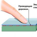
It is extremely important not to overheat the board itself during soldering. After all, there are paths in it. If they overheat, they may rise, which will disrupt the entire operation of the device.
The video will demonstrate how you can replace the USB connector on a laptop yourself:
Charging problems various devices via USB often occur when non-standard chargers are used. At the same time, charging occurs rather slowly and incompletely or completely absent.
It should also be said that charging via USB is not possible with all mobile devices. They have this port only for data transfer, and a separate round socket is used for charging.
The output current in computer USB is no more than half an ampere for USB 2.0, and for USB 3.0 – 0.9 A. For a number of devices, this may not be enough for a normal charge.
It happens that you have a charger at your disposal, but it does not charge your gadget (this may be indicated by a message on the display or there will be no charge indication). Such a charger is not supported by your device, and this may be due to the fact that a number of gadgets scan for the presence of a certain voltage on pins 2 and 3 before starting the charging process. For other devices, the presence of a jumper between these pins, as well as their potential, may be important.
Thus, if the device does not support the proposed type of charger, then the charging process will never begin.
In order for the device to start charging from the charger provided to it, it is necessary to provide the necessary voltages on the 2nd and 3rd USB pins. For different devices these voltages may also differ.
Many devices require that pins 2 and 3 have a jumper or resistance element whose value is no more than 200 ohms. Such changes can be made in the USB_AF socket, which is located in your memory. Then it will be possible to charge using a standard Data cable.
The Freelander Typhoon PD10 gadget requires the same connection circuit, but the charge voltage must be at 5.3 V.
If the charger does not have a USB_AF socket, and the cord comes out directly from the charger case, you can solder mini-USB or micro-USB plugs to the cable. Connections must be made as shown in the following picture:
Various products Apple has this connection option:
In the absence of a 200 kOhm resistance element on pins 4 and 5, Motorola devices cannot carry out a full charge.
For Samsung chargers Galaxy requires a jumper on pins 2 and 3, as well as a 200 kOhm resistor element on pins 4 and 5.
Full charge Samsung Galaxy Tab in gentle mode is recommended to be done using two resistors with a nominal value of 33 kOhm and 10 kOhm, as shown in the picture below:
A device such as E-ten can be charged by any charger, but only on the condition that pins 4 and 5 are connected by a jumper.
This scheme is implemented in the USB-OTG cable. But in this case it is necessary to use additional USB adapter dad-dad.
The Ginzzu GR-4415U universal charger and other similar devices have sockets with different resistor connections for charging iPhone/Apple and Samsung/HTC devices. The pinout of these ports looks like this:
To charge Garmin navigator, you need the same cable with a jumper on pins 4 and 5. But in this case, the device cannot be charged during operation. In order for the navigator to be recharged, it is necessary to replace the jumper with a resistor rated 18 kOhm.
Tablets usually require 1-1.5A to charge, but as mentioned earlier, USB ports will not be able to charge them properly as USB 3.0 will only output 900mA maximum.
Some tablet models have a round coaxial socket for charging. In this case, the positive pin of the mini-USB/micro-USB socket does not have a connection to the battery charge controller. According to some users of such tablets, if you connect the plus from the USB socket to the plus of the coaxial socket with a jumper, charging can be carried out via USB.
You can also make an adapter for connecting to a coaxial socket, as shown in the figure below:
Here are the jumper diagrams indicating the voltage and resistor values:
As a result, to charge various gadgets for non-native chargers, you need to make sure that charging produces a voltage of 5 V and a current of at least 500 mA, and make changes to the USB socket or plug according to the requirements of your device.
Convenient storage of radio components
This article provides general information about the USB standard, as well as pinoutUSB connector by colors of all types (USB, mini-USB, micro-USB, USB-3.0).
USB (Universal Serial Bus) connector is a universal-purpose serial bus, a modern way of connecting external devices to a personal computer. Replaces previously used connection methods (serial and parallel port, PS/2, Gameport, etc.) for common species peripheral devices - printers, mice, keyboards, joysticks, cameras, modems, etc. This connector also allows you to organize data exchange between a computer and a video camera, card reader, MP3 player, or external hard drive.
The advantage of the USB connector over other connectors is the ability to connect Plug&Play devices without the need to restart the computer or manual installation drivers. Plug&Play devices can be connected while the computer is running and be up and running within seconds.
When connecting a new device, first the hub (cable hub) receives high level via a data line, which reports that new equipment has arrived. Then the following steps follow:
- The Hub informs the Host computer that a new device has been connected.
- The host computer asks the hub which port the device was connected to.
- After receiving a response, the computer issues a command to activate this port and resets the bus.
- The hub generates a reset signal (RESET) with a duration of 10 ms. The output power current of the device is 100 mA. The device is now ready for use and has a default address.
The creation of USB is the result of collaboration between companies such as Compaq, NEC, Hewlett-Packard, Philips, Intel, Lucent and Microsoft. The USB standard was intended to replace the widely used serial port RS-232. USB generally makes work easier for the user and has a greater throughput than the RS-232 serial port. The first USB specification was developed in 1995 as a low-cost, universal interface for connecting external devices that did not require much data bandwidth.

Three USB versions
USB 1.1
Version USB 1.1 was designed to serve slow peripheral devices (Low-Speed) with a data transfer rate of 1.5 Mbit/s and fast devices (Full-Speed) with a data transfer rate of 12 Mbit/s. USB 1.1, however, was unable to compete with high speed interface, For example. FireWire (IEEE 1394) from Apple with data transfer rates up to 400 Mbps.
USB 2.0
In 1999, they began to think about the second generation of USB, which would be applicable to more complex devices (for example, digital video cameras). This new version, referred to as USB 2.0, was released in 2000 and provided maximum speed up to 480 Mbit/s in Hi-Speed mode and remains backward compatible with USB 1.1 (data transfer type: Full-Speed, Low-Speed).
USB 3.0
The third version (also referred to as Super-speed USB) was designed in November 2008, but was probably delayed until 2010 due to the financial crisis. USB 3.0 has more than 10 times the speed of USB 2.0 (up to 5 Gbit/s). The new design has 9 wires instead of the original 4 (the data bus already consists of 4 wires), however, this standard still supports USB 2.0 and provides lower power consumption. This allows you to use any combination of USB 2.0 and USB 3.0 devices and ports.
The USB connector has 4 pins. TO contacts DATA+ and DATA- a twisted pair is connected (two wires twisted together), and regular wires are connected to the VCC (+5 V) and GND pins. Then the entire cable (all 4 wires) is shielded with aluminum foil.
Below is the pinout (wiring) of all types USB connectors.
Types and pinout of USB connectors
USB cable pinout by color:

- +5 volts
- -Data
- +Data
- General
USB connector pinout diagram - type A:


USB connector pinout diagram - type B:


Cable wiring according to connector colors:mini (mini) and micro (micro) USB:

- +5 volts
- -Data
- +Data
- Not used / Shared
- General
Mini-USB connector pinout - type A:

Pinout of micro usb charging connector- The USB bus connector appeared around the beginning of 1990, and its main purpose was to be used in household radio equipment. Today, the micro USB connector has become extremely popular not only in household devices, but also in professional multimedia devices. However, its “everyday” origins are clearly visible in the fact that these plug-in format connectors are installed on almost any audio-video equipment, without exception.
The first connecting connectors differed from modern ones in their large sizes, although its socket was normally installed in small-sized portable devices. Over time, the sizes of USB connectors have acquired compact forms in various variants, such as MINI-USB, MICRO-USB and simply USB. These types of connecting devices made it possible to carry out its main functional purpose. At the same time, they differed significantly in size and ease of use from the earlier created analogue.
Device and pinout of micro usb charging connector
The micro usb connecting device consists of five contact pads; each pad is connected to an insulated mounting wire. For precise orientation of the connector when connecting to the mating part of the connector, a special chamfer on the edge is made on its upper shielding part. The contact pads of the connector are numbered from one to five, which are read from right to left. For clarity, this is shown in the picture below. The wiring diagram for the micro USB connector, as well as the purpose of its contacts isolated from each other, are shown in the table:
Micro USB pinout by wire color
The shielding shell also serves as a wire, but is not soldered to a separate contact pad.
Modern connecting devices such as micro USB connectors have fairly good performance characteristics and a relatively low price. Therefore, given the availability in trade huge amount various connecting wires of this type - repair of such auxiliary equipment is carried out extremely rarely. But still, if you have to replace a defective connector socket, then pinout the micro USB connector will not cause much trouble. Structurally well-made micro USB connectors, even despite their miniature dimensions, they will not allow you to make serious mistakes in installation.
Micro usb pinout— micro-USB desoldering is considered the most common type of repair of this type of device these days. Surely you have already encountered such a situation when you currently need a USB adapter, but you don’t have one at hand. Circumstances can be different - the device has broken down, has gone missing somewhere, is not on sale, its length is not enough, and so on. If you are familiar with the method of pinouting micro usb, then you can solve this problem with my own hands at home.
USB WIRE COLORS needed to perform USB CABLE repairs.
| Conclusion | Name | Wire color | Description |
|---|---|---|---|
| 1 | VCC | +5V | |
| 2 | D- | Data - | |
| 3 | D+ | Data + | |
| 4 | GND | Earth |
The heterogeneity of USB 2.0 connectors is shown in the figure below.
The name of one or another connector is indicated by letter designation indices.
Connector Model:
A - active action, power source - personal computer USB Host Controller
B - passive action, additional equipment- computer printer or scanner
Connector type:
M - male connector
F - socket
Connector dimensions:
no designation index
MINI
MICRO
USB MICRO-BM pin connector (M) is used for connection with a passive device (B); dimensions micro.
Micro USB pinout - sockets and pin connectors
The purpose of the wires in the USB connector is as follows:
- Red wire— +5v positive voltage relative to ground. Current limit - 0.5A
- White wire D-(-Data)
- Green wire D+(+Data)
- Black wire GND - common bus, ground, body - no voltage
Mini - micro connectors are provided with five contacts:
- Red color
- White D-
- Green D+
- ID - not connected in connectors “B”; in connectors “A” is shorted to GND to ensure “OTG” operation
- Black color GND ground
In addition to all of the above, a USB cable can have a core without insulation Shield - housing, braided shielding. This conductor is not assigned an identification number.
Correct perception of the connectors in the pictures:
All tables show the connector shown from its outer working side, and not from the side of the solder pads. The components that act as insulating elements in the diagram are light gray, segments made of metal are indicated in dark gray, and voids in the connector are marked in white.
USB wiring method
Standard USB does not cause any difficulties; you just need to take the drawing of the front side of the connector, geometrically transformed into a mirror image, and you can solder.
The pinout of the MINI and MICRO USB pin connectors is shown in the image below:
Five-pin connectors MINI and MICRO. In connector version “B” the fourth contact pad is not used. In option “A” the fourth contact pad is short-circuited to the GND bus. And the GND contact itself has the digital designation No5.