This article is the first in a planned series of articles on studying microcontroller programming. While studying various materials, I noticed that almost all of them begin with the fact that a beginner is asked to download (or use the library that comes with the development environment) for working with peripheral devices and use it to write his first program (usually blinking an LED).
This surprised me greatly. If you believe these articles, you don’t even need to read the documentation for the programmable controller to program. I was taught wisdom "hardware programming" completely different.
In this article, the path from the phrase “Yes, I want to try!” until the joyful wink of the LED will be much longer than that of other authors. I will try to reveal aspects of microcontroller programming that are hidden behind the use of library functions and ready-made examples.
If you intend to seriously study microcontroller programming, this article is for you. Perhaps it may also be of interest to those who have played enough with Arduino and want to get their hands on all the hardware capabilities of the hardware.
Selecting a microcontroller
Many may say that it is better to start learning microcontrollers with AVR, PIC, 8051 or something else. The issue is multifaceted and controversial. I know enough examples where people, having studied Cortex-M, programmed AVR, ARM7, etc. I myself started with Cortex-M3. If you are faced with a specific task, there is a lot of information on the Internet with comparisons various types microcontrollers and tasks solved with their help. This question was also raised on Habré, for example.We will assume that we have figured out the type of microcontroller. But the market offers a huge range of different modifications from different manufacturers. They differ in many parameters - from the size of flash memory to the number of analog inputs. For each task, the choice should be made individually. There are not and cannot be any general recommendations here. I will only note that it is worth starting your study with MK manufacturers who have the largest possible range. Then, when choosing an MK for a specific task, there is a fairly high chance that something from the presented range will suit you.
I chose STM32(although I think it’s better to start studying with MK from TexasInstruments - the documentation is very well compiled), because they are widespread among Russian developers electronics. If you have any problems or questions, you can easily find solutions on the forums. Another plus is the wide selection of demo boards from both the manufacturer and third-party organizations.
What do you need to study?
Unfortunately, to start programming a MK, just a PC is not enough. You'll have to get a demo board and programmer somewhere. Although this reduces competition in the labor market.I'm using a demo board myself. STM3220G-EVAL and programmer J-Link PRO. But for starters, it will be quite enough STM32F4DISCOVERY, which can be bought without any problems for a small amount.
All examples will be specifically for the debug board STM32F4DISCOVERY. At this stage, it will not be at all important to us that this board has an MCU based on the Cortex-M4 core. We will not be using its features and advantages over Cortex-M3 in the near future. We'll see what happens next.
If you have any other board based on STM32F2xx/STM32F4xx, you can work with it. In presenting the material, I will try to describe in as much detail as possible. Why we do it this way and not otherwise. I hope no one will have problems transferring examples to other hardware.
Development environment
As has already been mentioned several times, there are a sufficient number of development environments for ARM microcontrollers, both paid and not so much. And again I would like to omit the controversy on this matter. I'm using IAR Embedded Workbench for ARM 6.60. All examples will be in this environment. If you like (or your organization uses) something else (Keil, Eclipse, CCS, CooCoc, etc.) then this will not hurt you either. I will pay special attention to features related specifically to the development environment.Why a paid development environment?
Perhaps someone will not be entirely happy with the fact that I suggest using a paid development environment, but in IAR it is possible to get a temporary license without functionality restrictions, or an unlimited license with a code size limit (32KB for MK is a lot).
In addition, I will immediately note that for some MKs there are no free development environments. And unfortunately, these MKs are irreplaceable in some areas.
I will not describe the installation process.
Where to start?
Creating a Project
First, let's create an empty project. IAR allows you to create projects in ASM, C and C++. We will use C.An empty project with a main file will appear in front of us.

Now you need to configure the project to start working with “our” MK and debugger. MK installed on STM32F4DISCOVERY board STM32F407VG. It must be selected in the project properties (General Options->Target->Device):

When you select a target programmable processor, its description is loaded, which provides ample opportunities for debugging (this will be discussed below). In addition, a configuration file describing the available address space for the linker is automatically attached. If necessary, we will touch on the topic of the linker configuration file in future articles.
After this, you need to configure the debugger. Debugging of the program occurs directly “in the hardware”. This is done using a JTAG debugger. You can learn more about how this happens on Wikipedia. The ST-LINK/V2 debugger is integrated on the STM32F4DISCOVERY board. To work with the debugger, you must select its driver in the menu Debugger->Setup->Driver. It is also necessary to indicate that debugging should be carried out directly in the hardware. To do this you need to set the flag Debugger->Download->Use flash loader(s)
For those who saw the word Simulator
In theory, IAR allows you to debug programs using a simulator. But I have never seen it used in practice.
Now the project is ready for work (programming, filling and debugging).
"TZ" for the first project
Let's summarize: The MK and debug board have been selected, the project has been prepared. It's time to decide on the task.Let's not deviate from the classics. The first project will be a flashing LED. Fortunately, there are plenty of them on the board. What does this mean from a programming point of view? The first thing you need to do is study the circuit diagram of the demo board and understand how the LED “starts up”.
available on the manufacturer's website. IN this description there is even a separate section about LEDs on the board - 4.4 LEDs. For example, we will use User LD3. Let's find it in the diagram: 
The simplest analysis of the circuit suggests that in order to “light up” the LED, you need to apply “1” to the MK pin (which for this MK corresponds to 3.3V). Switching off is done by applying “0” to this pin. In the diagram this pin is designated PD13(this is probably the most important information from this document).
As a result, we can write “TK” for our first program:
The program for the MK must transfer the state of the MK PD13 pin from state “0” to state “1” and back with a certain periodicity that is discernible to the human eye (an important note, if the LED blinks too often the eye may not be able to distinguish this).
Before you start programming, or a little theory
Before we begin to implement our technical specifications, it is necessary to understand how MK is managed.Let's start with the fact that any MK includes a core, memory and peripheral units. I think that with memory everything is clear for now. Let me just mention that the STM32 has flash memory in which the MK program is stored (in general, this is not a true statement, the program can be stored in external non-volatile memory, but we’ll ignore that for now) and other data, including user data. There is also SRAM - random access memory.
The core is the part of the microcontroller that executes one stream of commands. In our MK the core type is Cortex-M4. The MK core can be compared to the processor in a PC. It can only execute commands and transfer data to other units (processors with integrated graphics accelerators are not taken into account in this comparison).
At the same time, the MK manufacturer does not develop the core. The core is purchased from ARM Limited. The main difference between different MKs is in the periphery.
Peripheral blocks are blocks that interact with the “outside world” or perform specific functions that are inaccessible to the MK core. Modern MCUs (including STM32) contain a huge range of peripheral units. Peripheral blocks are designed to solve various problems, from reading the voltage value from the analog input of the MK to transmitting data to external devices via the SPI bus.
Unlike the MK core, peripheral units do not execute instructions. They only execute kernel commands. In this case, the participation of the kernel when executing the command is not required.
Example
An example is the UART block, which is designed to receive and transmit data from the MK to external devices. The kernel only needs to configure the block and give it data for transmission. After this, the kernel can continue executing instructions. The peripheral unit is responsible for controlling the corresponding MK output for data transmission in accordance with the protocol. The peripheral unit itself transfers the MK output to the required state “0” or “1” at the right time, carrying out the transmission.
Interaction of the core with the peripheral unit
The interaction of the MK core with the peripheral unit is carried out using special registers (there is also interaction through the interrupt mechanism and DMA, but more on that in the following posts). From the kernel's point of view, this is simply a piece of memory with a specific address, that's just not true. Writing data to a special register is equivalent to transmitting a command or data to a peripheral unit. Reading - receiving data from a block or reading its state. The description of peripheral blocks and their special registers takes up the lion's share of the MK description.IMPORTANT: After writing data to a special register and then reading it, you can get completely different data. For example, sending data to the UART block to send, and reading data received by the block from external device, is carried out using the same register.
Special registers are usually divided into bit fields. One (or more) bits control a specific peripheral block parameter, usually independently. For example, different bits of one register control the state of different MK outputs.
Remember C
If you are a C guru, you can safely skip this section. It is intended primarily for those who were taught (or who learned themselves) to program for a PC. Experience shows that people often do not remember important commands. Here I will briefly remind you about bitwise operations and working directly with memory at its address.Writing data to a memory address
Let's assume that by reading the description of the peripheral unit, we realized that for it correct operation you need to write the number 0x3B into it. The special register address is 0x60004012. The register is 32-bit.
If you don’t immediately know how to do this, I’ll try to describe the chain of reasoning to get the correct command.
The value 0x60004012 is nothing more than the value of a pointer to a memory location. This is exactly what we need to indicate in our program, that is, to make a type conversion according to the syntax of the C language:
(unsigned long*)(0x60004012)
So we have a pointer to an element. Now you need to write the required value into this element. This is done by dereferencing the pointer. Thus we get the correct command:
*(unsigned long*)(0x60004012) = 0x3B;
Setting arbitrary bits to 1
Let's assume that we want to set bits 7 and 1 at address 0x60004012 to "1" without changing the value of all other bits in the register. To do this, you need to use the binary operation |. I'll give you the correct answer right away:
*(unsigned long*)(0x60004012) |= 0x82;
Pay attention to 2 facts. Bits are counted from zero, not from first. This operation actually takes at least 3 clock cycles - reading the value, modifying it, writing it. Sometimes this is not acceptable because between the read and write, the value of one of the bits that we are not allowed to change may have been changed by the peripheral unit. Don’t forget about this feature, otherwise bugs may appear that are extremely difficult to catch.
Setting arbitrary bits to 0
Let's assume that we want to set bits 7 and 1 at address 0x60004012 to "0" without changing the value of all other bits in the register. To do this, you need to use the binary & operator. I'll give you the correct answer right away:
*(unsigned long*)(0x60004012) &= 0xFFFFFF7D;
Or its simpler notation (don’t worry about the extra operation, the compiler will calculate everything in advance even with minimal optimization):
*(unsigned long*)(0x60004012) &= (~0x82);
Some features of programs for MK
Here I will try to describe some features of programs for MK that are important to remember. Things are quite obvious, but still.The program has no end
Unlike most PC programs, the MK program should never end, NEVER! What exactly will MK have to do after completing your program? The question is practically rhetorical. Therefore, do not forget to make sure that you have not forgotten the eternal cycle. If desired, you can put the MK into sleep mode.
Use integer variables
Despite the fact that we use a microcontroller with a Cortex-M4 core, which performs operations on floating point numbers in hardware, I advise you not to use them. In a microcontroller without support for such operations, the computation time will be simply enormous.
Avoid dynamic memory allocation
This is just advice. The reason is simple - there is not enough memory. I have often encountered libraries that had “slow memory leaks”. It was very unpleasant when, after several weeks of stable operation, the MK crashed with an error. It is better to think through the architecture of your program in advance so that you do not have to use dynamic memory allocation.
If you still want to use it, carefully study the work of the memory manager or write your own.
Let's get to work!
Work on a program for MK always begins with reading the documentation. For our MK it is available on the manufacturer’s website. There are a lot of pages, but read them all Bye no need. As already mentioned, most of the documentation consists of a description of the peripheral units and their registers. I also want to draw your attention to the fact that this Reference Manual was written not for one MK, but for several lines. This suggests that the code will be portable when moving to other MKs in these lines (unless, of course, you try to use peripheral units that are not in the MK you are using).First of all, you need to decide which blocks you want to work with. To do this, just study the sections Introduction And Main features.
Direct control of the state of the MK pins is carried out using the GPIO block. As indicated in the documentation, the STM32 MCU can have up to 11 independent GPIO blocks. Various peripheral GPIO blocks are commonly called ports. The ports are designated by letters A through K. Each port can contain up to 16 pins. As we noted earlier, the LED is connected to pin PD13. This means that this pin is controlled by the peripheral unit GPIO port D. Pin number 13.
We won’t need any other peripheral units this time.
Peripheral clock control
To reduce power consumption of the MK, almost all peripheral units are turned off after turning on the MK. The block is turned on/off by applying/stopping the supply of a clock signal to its input. For correct operation, it is necessary to configure the MK clock signal controller so that the required peripheral unit receives a clock signal.Important: Peripheral unit cannot start operation straightaway after the clock signal is turned on. You need to wait a few ticks until it “starts”. People using peripheral libraries often don't even know about this feature.
Registers are responsible for enabling clocking of peripheral units RCC XXX peripheral clock enable register.In place of XXX there can be tires AHB1, AHB2, AHB3, APB1 and APB2. After carefully studying the description of the corresponding registers, we can conclude that the clocking of the GPIOD peripheral block is turned on by setting “1” in the third bit of the register RCC AHB1 peripheral clock enable register (RCC_AHB1ENR):
Now you need to figure out how to find out the address of the register itself RCC_AHB1ENR.
Comment: The description of the STM32 MK clocking system is worthy of a separate article. If readers would like, I will cover this section in more detail in one of the following articles.
Determining special register addresses
Determining the addresses of special registers must begin by reading the section Memory map in Reference manual. You can see that each block is allocated its own section of the address space. For example, for the RCC block this is the section 0x4002 3800 - 0x4002 3BFF:

To obtain the register address, it is necessary to add to the initial value of the address space of the RCC block Addr. offset the required register. Addresses offset is also indicated in the register description (see screenshot above).
As a result, we have determined the register address RCC_AHB1ENR- 0x4002 3830.
GPIO block
For a general understanding of the GPIO block, I highly recommend reading the entire section of the Reference Manual. For now you can not pay much attention to Alternate mode. We'll leave that for later.Now our task is to learn how to manage the state of MK pins. Let's move straight to the description of the GPIO registers.
Operating mode
First of all, you need to set the operating mode of pin 13 of port D as General purpose output mode, which means that the GPIO block will control the state of the MK pin. The operating mode of MK pins is controlled using a register GPIO port mode register (GPIOx_MODER) (x = A..I/J/K):
As can be seen from the description, to make the adjustment we require, we need to write the value 01b into 26-27 bits of the register GPIOx_MODER. The register address can be determined using the same method as described above.
Configuring the operation parameters of the output pins of the GPIO port
The GPIO block allows you to apply additional settings for the output pins of the port. These settings are made in the registers:- GPIO port output type register (GPIOx_OTYPER)- set the output type push-pull or open-drain
- GPIO port output speed register (GPIOx_OSPEEDR)- set the speed of the output
Setting the value on the MK pin
Finally, we have come to the moment of controlling the output state of the MK. There are two methods for setting the output value on a specific MK pin.We use the GPIO port bit set/reset register (GPIOx_BSRR)

Writing a “0” or “1” to bits 0-16 causes a corresponding change in the state of the port pins. In order to set a certain value at the output of one or more MK pins and not change the state of the others, it will be necessary to use the operation of modifying individual bits. This operation is performed in at least 3 cycles. If it is necessary to write 1s to some bits and 0s to others, then at least 4 clock cycles will be required. This method is best used to change the state of an output to its opposite state if its original state is unknown.
GPIO port bit set/reset register (GPIOx_BSRR)

Unlike the previous method, writing 0 to any of the bits of this register will not lead to anything (and in general, all bits are write-only!). Writing 1 to bits 0-15 will result in a “1” being set at the corresponding output of the MK. Writing 1 to bits 16-31 will set “0” at the corresponding output of the MK. This method is preferable to the previous one if you need to set a specific value on the “MK” pin rather than change it.
Let's light up the LED!
Having found the addresses of all the necessary registers, you can write a program that turns on the LED:void main() ( //Enable port D clocking *(unsigned long*)(0x40023830) |= 0x8; //little delay for GPIOD get ready volatile unsigned long i=0; i++; i++; i++; i=0; / /Set PD13 as General purpose output *(unsigned long*)(0x40020C00) = (*(unsigned long*)(0x40020C00)& (~0x0C000000)) | (0x04000000); //Turn LED ON *(unsigned long*) (0x40020C14) |= 0x2000; while(1);
Can be compiled ( Project->Compile) and fill ( Project->Download->Download active application). Or run debugging ( Project->Dpwnload and Debug) and start execution (F5).
The LED lit up!
Flashing LED
Flashing of the LED is nothing more than alternate turning on and off with a delay between these actions. The easiest way is to put the on and off in an eternal loop, and insert a delay between them.void main() ( //Enable port D clocking *(unsigned long*)(0x40023830) |= 0x8; //little delay for GPIOD get ready volatile unsigned long i=0; i++; i++; i++; i=0; / /Set PD13 as General purpose output *(unsigned long*)(0x40020C00) = (*(unsigned long*)(0x40020C00)& (~0x0C000000)) | (0x04000000); while(1) ( //Turn LED ON *( unsigned long*)(0x40020C14) |= 0x2000; //Delay for(i=0; i<1000000 ;++i); //Turn LED OFF *(unsigned long*)(0x40020C14) &= ~0x2000; //Delay for(i=0; i<1000000 ;++i); } }
The delay value of 1,000,000 was selected experimentally so that the blinking period of the LED was visible to the eye, but was not too long.
Optimizing the algorithm
The disadvantage of the chosen LED blinking approach is that the MK core spends most of its time in empty loops, although it could be doing something useful (in our example there are no other tasks, but they will appear in the future).In order to avoid this, a cycle counter is usually used, and the state of the MK pin switches when the program goes through a certain number of cycles.
void main() ( //Enable port D clocking *(unsigned long*)(0x40023830) |= 0x8; //little delay for GPIOD get ready volatile unsigned long i=0; i++; i++; i++; i=0; / /Set PD13 as General purpose output *(unsigned long*)(0x40020C00) = (*(unsigned long*)(0x40020C00)& (~0x0C000000)) | (0x04000000); while(1) ( i++; if(!(i) %2000000)) ( //Turn LED ON *(unsigned long*)(0x40020С14) |= 0x2020; ) else if(!(i%1000000)) ( //Turn LED OFF *(unsigned long*)(0x40020С14) & = ~0x2000; ) ) )
But even here it will not be without problems; with a change in the number of commands executed within the cycle, the period of blinking of the LED (or the period of execution of other commands in the cycle) will change. But at this stage we cannot fight this.
A little about debugging
IAR allows you to debug an application directly on the hardware. Everything looks almost the same as debugging a PC application. There is a mode for step-by-step execution, entering a function, viewing the values of variables (In debugging mode View->Watch->Watch1/4).
But in addition to this, it is possible to view the values of kernel registers, special registers of peripheral units (View->Register), etc.
I strongly recommend that you familiarize yourself with the capabilities of the debugger while learning MK programming.
A few words in conclusion
Perhaps many will say that manually writing addresses in a program is not correct, since the manufacturer provides files with definitions of registers and bit fields, libraries for working with peripherals and other tools that make life easier for the developer. I completely agree with this, but I still believe that the first steps in programming an MK must be taken by digging through the documentation manually, independently determining the necessary registers and bit fields. You don’t have to use this in the future, but you definitely need to know how to do it.Here are just a few reasons for this statement:
- Sometimes libraries from the manufacturer contain errors! I once almost missed a project deadline because of this. I re-soldered the chip several times, thinking that the crystal had been damaged during soldering (this had happened before). The problem was that the address of the special register was entered incorrectly in the library. This usually happens with MK or MK lines that have just entered the market.
- Libraries for working with peripherals from some manufacturers do not implement all the capabilities of peripheral units. I especially sinned with this Luminary Micro, which were later bought by TI. I had to write the initialization of the peripherals manually.
- Many people get used to starting MK programming by studying examples. I believe that first you need to decide what allows you to implement MK. This can only be understood by reading the documentation. If something is not in the examples, this does not mean that the hardware does not support it. The last example is PTP STM32 hardware support. Of course, you can find something online, but it is not included in the standard set from the manufacturer.
- The drivers of peripheral units from some manufacturers are so unoptimized that switching the state of a pin using the library takes up to 20 clock cycles. This is an unaffordable luxury for some tasks.
Thanks to everyone who read my post, it turned out much more than I expected at the beginning.
I look forward to your comments and reasoned criticism. If those who read it have the desire, I will try to continue the series of articles. Perhaps anyone has ideas about topics that would be worth covering - I'd be glad to hear them.
Published 08/09/2016
Microcontrollers STM32 are becoming increasingly popular due to their power, fairly diverse peripherals, and flexibility. We will start studying using a budget test board, the cost of which does not exceed $2 (from the Chinese). We will also need ST-Link programmer, the cost of which is about $2.5 (from the Chinese). Such amounts of expenses are available to both students and schoolchildren, so it is from this budget option I suggest we start.

This microcontroller is not the most powerful among STM32, but not the weakest either. There are various boards with STM32, including Discovery which cost about $20. On such boards, almost everything is the same as on our board, plus a programmer. In our case, we will use the programmer separately.
Microcontroller STM32F103C8. Characteristics
- ARM 32-bit Cortex-M3 core
- Maximum frequency 72MHz
- 64Kb Flash memory for programs
- 20Kb SRAM memory
- Power supply 2.0 … 3.3V
- 2 x 12-bit ADC (0 ... 3.6V)
- DMA controller
- 37 5V tolerant inputs/outputs
- 4 16-bit timers
- 2 watchdog timers
- I2C – 2 buses
- USART – 3 buses
- SPI – 2 buses
- USB 2.0 full-speed interface
- RTC – built-in clock
Available on STM32F103C8 board

- Output ports A0-A12, B0-B1, B3-B15, C13-C15
- Micro-USB through which you can power the board. The board has a 3.3V voltage stabilizer. 3.3V or 5V power can be supplied to the corresponding pins on the board.
- Button Reset
- Two jumpers BOOT0 And BOOT1. We will use it during flashing via UART.
- Two quartz 8 MHz and 32768 Hz. The microcontroller has a frequency multiplier, so with an 8 MHz quartz we can reach the maximum controller frequency of 72 MHz.
- Two LEDs. PWR– signals that power is supplied. PC13– connected to the output C13.
- Connector for programmer ST-Link.
So, let's start by trying to flash the microcontroller. This can be done via USART, or using a programmer ST-Link.
You can download the test file for firmware. The program flashes the LED on the board.
STM32 firmware using USB-Uart adapter for Windows
In system memory STM32 There is Bootloader. Bootloader is recorded at the production stage and any microcontroller STM32 can be programmed via interface USART using a USART-USB adapter. Such adapters are most often made on the basis of popular microcircuits FT232RL. First of all, connect the adapter to the computer and install the drivers (if required). You can download drivers from the manufacturer's website FT232RL– ftdichip.com. You need to download drivers VCP(virtual com port). After installing the drivers, a virtual serial port should appear on your computer.


Connecting RX And TX outputs to the corresponding pins USART1 microcontroller. RX connect the adapter to TX microcontroller (A9). TX connect the adapter to RX microcontroller (A10). Since USART-USB has 3.3V power outputs, we will supply power to the board from it.

To put the microcontroller into programming mode, you need to set the pins BOOT0 And BOOT1 to the desired state and reboot it with the button Reset or turn off and on the power of the microcontroller. For this we have jumpers. Different combinations force the microcontroller into different modes. We are only interested in one mode. To do this, the microcontroller has BOOT0 there should be a logical one, and the output BOOT1– logical zero. On the board this is the following jumper position:

After pressing the button Reset or disconnecting and connecting the power, the microcontroller must enter programming mode.
Firmware software
If we use a USB-UART adapter, the port name will be something like this /dev/ttyUSB0
Get chip information
Result:
We read from the chip into the file dump.bin
sudo stm32flash -r dump.bin /dev/ttyUSB0Write to the chip
sudo stm32flash -w dump.bin -v -g 0x0 /dev/ttyUSB0Result:
Stm32flash 0.4 http://stm32flash.googlecode.com/ Using Parser: Raw BINARY Interface serial_posix: 57600 8E1 Version: 0x22 Option 1: 0x00 Option 2: 0x00 Device ID: 0x0410 (Medium-density) - RAM: 20KiB (512b reserved by bootloader) - Flash: 128KiB (sector size: 4x1024) - Option RAM: 16b - System RAM: 2KiB Write to memory Erasing memory Wrote and verified address 0x08012900 (100.00%) Done. Starting execution at address 0x08000000... done.
Firmware STM32 using ST-Link programmer for Windows
When using a programmer ST-Link conclusions BOOT0 And BOOT1 are not used and must be in the standard position for normal operation of the controller.

(Book in Russian)
STM32 marking
| Device family | Product type | Device subfamily | Pin count | Flash memory size | Package | Temperature range |
|---|---|---|---|---|---|---|
| STM32 = ARM-based 32-bit microcontroller | F = General-purpose L = Ultra-low-power TS=TouchScreen W = wireless system-on-chip | 60 = multitouch resistive 103 = performance line | F = 20 pins G = 28 pins K = 32 pins T = 36 pins H = 40 pins C = 48/49 pins R = 64 pins O = 90 pins V = 100 pins Z = 144 pins I = 176 pins B = 208 pins N = 216 pins | 4 = 16 Kbytes of Flash memory 6 = 32 Kbytes of Flash memory 8 = 64 Kbytes of Flash memory B = 128 Kbytes of Flash memory Z = 192 Kbytes of Flash memory C = 256 Kbytes of Flash memory D = 384 Kbytes of Flash memory E = 512 Kbytes of Flash memory F = 768 Kbytes of Flash memory G = 1024 Kbytes of Flash memory I = 2048 Kbytes of Flash memory | H = UFBGA N=TFBGA P = TSSOP T = LQFP U = V/UFQFPN Y = WLCSP | 6 = Industrial temperature range, –40…+85 °C. 7 = Industrial temperature range, -40…+ 105 °C. |
| STM32 | F | 103 | C | 8 | T | 6 |
How to remove write/read protection?
If you received a board with STM32F103, but the programmer does not see it, this means that the Chinese have protected the Flash memory of the microcontroller. The question “why?” let's ignore it. To remove the blocking, we will connect a UART adapter and program through it. We set the jumpers for programming and off we go:
I will do this from Ubuntu using the stm32flash utility.
1. Check whether the microcontroller is visible:
Sudo stm32flash /dev/ttyUSB0
You should get something like this:
Stm32flash 0.4 http://stm32flash.googlecode.com/ Interface serial_posix: 57600 8E1 Version: 0x22 Option 1: 0x00 Option 2: 0x00 Device ID: 0x0410 (Medium-density) - RAM: 20KiB (512b reserved by bootloader) - Flash: 128KiB (sector size: 4x1024) - Option RAM: 16b - System RAM: 2KiB
2. Remove read protection and then write protection:
Sudo stm32flash -k /dev/ttyUSB0 stm32flash 0.4 http://stm32flash.googlecode.com/ Interface serial_posix: 57600 8E1 Version: 0x22 Option 1: 0x00 Option 2: 0x00 Device ID: 0x0410 (Medium-density) - RAM: 20KiB ( 512b reserved by bootloader) - Flash: 128KiB (sector size: 4x1024) - Option RAM: 16b - System RAM: 2KiB Read-UnProtecting flash Done. sudo stm32flash -u /dev/ttyUSB0 stm32flash 0.4 http://stm32flash.googlecode.com/ Interface serial_posix: 57600 8E1 Version: 0x22 Option 1: 0x00 Option 2: 0x00 Device ID: 0x0410 (Medium-density) - RAM: 20KiB ( 512b reserved by bootloader) - Flash: 128KiB (sector size: 4x1024) - Option RAM: 16b - System RAM: 2KiB Write-unprotecting flash Done.
Now you can work normally with the microcontroller.
Some of the stm32 microcontrollers support the USB DFU protocol (a list of them can be found in app note AN3156), the firmware can be uploaded to such MCUs via regular USB, using for example DFuSe demo from ST, or open source dfu-util. Everything is clear with this option and I will not describe it.
For the same MKs (in particular, the one used in the BluePill board - STM32F103C8T6), which are deprived of DFU support, one way or another you need a programmer, for example ST-Link V2 Mini
Device pinout:

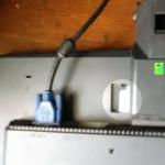
Connecting to the board is simple:
ST-Link STM32F103C8T6 3.3V --- 3.3V GND --- GND SWDIO --- DIO SWCLK --- DCLK

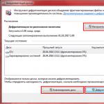
You also need the ST-Link Utility, you can download it from the official website st.com - link. When connecting for the first time, it would be a good idea to update the firmware of the programmer itself. Select ST-LINK -> firmware update, if more recent firmware is available, then there will be something like this:

Select Yes >>>>, the firmware is updated.
Next, open the actual firmware file and select Target -> Connect. Information about your MK will also appear in the utility status window - this means that the programmer is connected correctly and the utility can contact the MK. Example:

Then you need to do complete cleaning chip, select Target -> Erase Chip

If, for example, my firmware from the controller post for pedals and buttons has already been uploaded and needs to be updated or re-uploaded, then the programmer will not be able to connect to the board so easily (because I use SWD pins as regular GPIOs). In this case there are two options:
- rearrange both yellow jumpers. In this case, the board will be loaded directly into your internal bootloader
- you can do the so-called Connect under Reset. For him the sequence will be like this:
- in ST-Link Utility select Target -> Settings
- in Reset Mode select Hardware Reset
- press and hold the Reset button on the board
- Click OK in ST-Link Utility
- release the Reset button on the board
PS. If you have an SMT32F4Discovery development board, then it already has a programmer in it and it can also be used to flash another board. In this case, you need to use the SWD connector of the STM32F4Discovery and remove both jumpers CN3. The SWD connector has the following pinout:

In recent years, 32-bit microcontrollers (MCUs) based on ARM processors have been rapidly conquering the world of electronics. This breakthrough is due to their high performance, perfect architecture, low energy consumption, low cost and advanced programming tools.
BRIEF HISTORY
The name ARM is an acronym for Advanced RISC Machines, where RISC (Reduced Instruction Set Computer) stands for reduced instruction set processor architecture. The overwhelming number of popular microcontrollers, such as the PIC and AVR families, also have a RISC architecture, which makes it possible to increase performance by simplifying the decoding of instructions and accelerating their execution. The emergence of advanced and productive 32-bit ARM microcontrollers allows us to move on to solving more complex problems that 8 and 16-bit MCUs can no longer cope with. The ARM microprocessor architecture with a 32-bit core and RISC instruction set was developed by the British company ARM Ltd, which exclusively develops kernels, compilers and debugging tools. The company does not produce MKs, but sells licenses for their production. MK ARM is one of the fastest growing segments of the MK market. These devices use energy-saving technologies, therefore they are widely used in embedded systems and dominate the market mobile devices, for which low power consumption is important. In addition, ARM microcontrollers are actively used in communications, portable and embedded devices where high performance is required. A feature of the ARM architecture is the computing core of the processor, which is not equipped with any additional elements. Each processor developer must independently equip this core with the necessary blocks for their specific tasks. This approach has worked well for large chip manufacturers, although it was initially focused on classic processor solutions. ARM processors have already gone through several stages of development and are well known for the ARM7, ARM9, ARM11 and Cortex families. The latter is divided into subfamilies of classic CortexA processors, CortexR real-time processors and CortexM microprocessor cores. It was the CortexM cores that became the basis for the development of a large class of 32-bit microcontrollers. They differ from other variants of the Cortex architecture primarily in the use of the 16-bit Thumb2 instruction set. This set combined the performance and compactness of “classic” ARM and Thumb instructions and was developed specifically for working with the C and C++ languages, which significantly improves code quality. The great advantage of MCUs built on the CortexM core is their software compatibility, which theoretically allows the use program code in the language high level in models from different manufacturers. In addition to indicating the area of application of the core, MK developers indicate the performance of the CortexM core on a ten-point scale. Today, the most popular options are CortexM3 and CortexM4. MCUs with ARM architecture are produced by companies such as Analog Devices, Atmel, Xilinx, Altera, Cirrus Logic, Intel, Marvell, NXP, STMicroelectronics, Samsung, LG, MediaTek, MStar, Qualcomm, SonyEricsson, Texas Instruments, nVidia, Freescale, Milander, HiSilicon and others.
Thanks to the optimized architecture, the cost of MCUs based on the CortexM core is in some cases even lower than that of many 8-bit devices. “Younger” models can currently be purchased for 30 rubles. for the body, which creates competition for previous generations of MK. STM32 MICROCONTROLLERS Let's consider the most affordable and widespread MCU of the STM32F100 family from STMicroelectronics, which is one of the world's leading manufacturers of MCUs. The company recently announced the start of production of a 32-bit MK that takes advantage of industrial
STM32 cores in low-cost applications. MCUs of the STM32F100 Value line family are designed for devices where the performance of 16-bit MCUs is not enough, and the rich functionality of “regular” 32-bit devices is redundant. The STM32F100 line of MCUs is based on a modern ARM CortexM3 core with peripherals optimized for use in typical applications where 16-bit MCUs were used. The performance of the STM32F100 MCU at 24 MHz is superior to most 16-bit MCUs. This line includes devices with various parameters:
● from 16 to 128 kbytes of program flash memory;
● from 4 to 8 kbytes of RAM;
● up to 80 GPIO input/output ports;
● up to nine 16-bit timers with advanced functions;
● two watchdog timers;
● 16-channel high-speed 12-bit ADC;
● two 12-bit DACs with built-in signal generators;
● up to three UART interfaces supporting IrDA, LIN and ISO7816 modes;
● up to two SPI interfaces;
● up to two I2C interfaces supporting SMBus and PMBus modes;
● 7-channel direct memory access (DMA);
● CEC (Consumer Electronics Control) interface included in the HDMI standard;
● real time clock (RTC);
● NVIC nested interrupt controller.
The functional diagram of the STM32F100 is shown in Figure 1.
Rice. 1. Architecture of the MK line STM32F100
An additional convenience is the pin compatibility of the devices, which allows, if necessary, to use any MK of the family with greater functionality and memory without reworking the printed circuit board. The STM32F100 line of controllers is produced in three types LQFP48, LQFP64 and LQFP100 packages, having 48, 64 and 100 pins, respectively. The assignment of the pins is presented in Figures 2, 3 and 4. Such cases can be installed on printed circuit boards without the use of special equipment, which is a significant factor in small-scale production.

Rice. 2. STM32 MCU in LQFP48 package Fig. 3. STM32 MCU in LQFP64 package

Rice. 4. STM32 MCU in LQFP100 package
STM32F100 is an affordable and optimized device based on the CortexM3 core, supported by an advanced development environment for the STM32 family of microcontrollers, which contains
Free libraries for all peripherals, including motor control and touch keyboards.
CONNECTION DIAGRAM STM32F100C4
Let's consider the practical use of MK using the example of the simple device STM32F100C4, which, however, contains all the main blocks of the STM32F100 line. Fundamental electrical diagram inclusion of STM32F100C4 is shown in Figure 5. 
Rice. 5. Connection diagram for MK STM32F100C4
Capacitor C1 ensures that the MK is reset when the power is turned on, and capacitors C2-C6 filter the supply voltage. Resistors R1 and R2 limit the signal current of the MK pins. As a source clock frequency An internal oscillator is used, so there is no need to use an external crystal resonator. 
Inputs BOOT0 and BOOT1 allow you to select the method of loading the MK when turning on the power in accordance with the table. The BOOT0 input is connected to the zero potential bus through resistor R2, which protects the BOOT0 pin from a short circuit when used as an output port of PB2. Using connector J1 and one jumper, you can change the potential at the BOOT0 input, thereby determining how the MK is loaded - from flash memory or from the built-in bootloader. If you need to load the MK from RAM, a similar connector with a jumper can be connected to the BOOT1 input.
Programming of the MK is carried out via the UART1 serial port or through special programmers - JTAG or STLink debuggers. The latter is part of the popular debugging device STM32VLDISCOVERY, shown in Figure 6. On the STM32VLDIS COVERY board, the 4-pin connector of the programmer - STLink debugger - is designated SWD. The author of the article suggests programming the MK via the UART1 serial port, since it is much simpler, does not require special equipment and is not inferior in speed to JTAG or ST Link. As a control device capable of generating commands and displaying the results of the MK program, as well as as a programmer, you can use any personal computer(PC) with a serial COM port or USB port with a USBRS232 converter.
To interface the COM port of a PC with a MK, any converter of RS232 signals into logical signal levels from 0 to 3.3 V, for example, the ADM3232 microcircuit, is suitable. The TXD transmission line of the computer serial port, after the level converter, should be connected to the PA10 input of the microcontroller, and the RXD receiver line, through a similar converter, to the PA9 output.
If you need to use a non-volatile MK clock, you should connect a CR2032 battery with a voltage of 3 V and a quartz resonator with a frequency of 32768 Hz to it. For this purpose, the MK is equipped with Vbat/GND and OSC32_IN/OSC32_OUT pins. The Vbat pin must first be disconnected from the 3.3 V power bus.
The remaining free terminals of the MK can be used as needed. To do this, they should be connected to the connectors that are located around the perimeter of the printed circuit board for the MK, by analogy with the popular Arduino devices and the STM32VLDISCOVERY debug board. 
Rice. 6. Debug device STM32VLDISCOVERY

Electrical circuit diagram STM32VLDISCOVERY.
Thus, depending on the purpose and method of using the MK, you can connect the necessary elements to it to use other functional blocks and ports, for example, ADC, DAC, SPI, I2C, etc. In the future, these devices will be considered in more detail.
PROGRAMMING
Today, many companies offer tools for creating and debugging programs for STM32 microcontrollers. These include Keil from ARM Ltd, IAR Embedded Workbench for ARM, Atol lic TrueStudio, CooCox IDE, GCC and Eclipse IDE. The developer can choose the software according to his preference. Below we will describe the Keil uVision 4 toolkit from the company Keil, which supports a huge number of types of microcontrollers, has a developed system of debugging tools and can be used for free with restrictions on the size of the generated code of 32 kbytes (which, in fact, is the maximum for the microcontrollers under consideration).
Simple and quick start with CooCox CoIDE.
So let's get started. Go to the official CooCox website and download the latest version of CooCox CoIDE. To download you need to register, registration is simple and free. Then install the downloaded file and run it.
CooCox CoIDE- a development environment based on Eclipse, which, in addition to STM32, supports a bunch of other families of microcontrollers: Freescale, Holtek, NXP, Nuvoton, TI, Atmel SAM, Energy Micro, etc. With each new version of CoIDE, the list of microcontrollers is constantly updated. After successfully installing CoIDE, run:

The Step 1 start window will appear, in which you need to select the manufacturer of our microcontroller. Press ST and go to Step 2 (selecting a microcontroller), in which you need to select specific model. We have STM32F100RBT6B, so click on the corresponding model:

On the right, the Help window displays brief characteristics each chip. After selecting the microcontroller we need, we proceed to the third step, Step 3 - to selecting the necessary libraries for work:

Let's create a simple project for blinking an LED, as is customary for learning microcontrollers.
To do this, we need the GPIO library, when enabled, CoIDE will ask you to create new project. Click Yes on this proposal, indicate the folder where our project will be stored and its name. At the same time, CoIDE will connect to the project 3 others necessary for the library to work, and will also create all the necessary project structure:

Another good thing about CoIDE is that it has the ability to load examples directly into the development environment. In the Components tab you can see that there are examples for almost every library, click on GPIO (with 4 examples) and see them:

You can add your own examples there. As you can see in the screenshot above, the examples already contain code for blinking the GPIO_Blink LED. You can click the add button and it will be added to the project, but as an included file, so we will do it differently and simply copy the entire example code into the main.c file. The only thing is to replace the void GPIO_Blink(void) line with int main(void). So, press F7 (or select Project->Build from the menu) to compile the project and... no such luck!

The environment needs a GCC compiler, but we don't have one. Therefore, go to the GNU Tools for ARM Embedded Processors page, select your OS type on the right and download the latest version of the toolchain. Then we run the file and install gcc toolchain. Next, in the CoIDE settings we will indicate the correct path to the toolchain:

Press F7 again (Project->Build) and see that the compilation was successful:

All that remains is to flash the microcontroller. To do this, when USB help We connect our board to the computer. Then, in the debugger settings you need to install ST-Link; to do this, select Project->Configuration in the menu and open the Debugger tab. Select ST-Link from the drop-down list and close the window:

Let's try to flash the MK. In the menu, select Flash->Program Download (or click on the corresponding icon on the toolbar) and see that the MK has been successfully flashed:
We see a blinking LED on the board, I think it makes no sense to provide a video or photo, because... everyone saw it.
Also, various debugging modes work in CoIDE; to do this, press CTRL+F5 (or in the Debug->Debug menu):

That's all. As you can see, setting up and working with CoIDE is very simple. I hope this article will encourage you to study very promising and inexpensive STM32 microcontrollers.
To create a minimal project we will need: a stm32 controller (I have a stm32f103), some wires, an LED (for testing).
We won't even hang quartz, so as not to complicate the process.
It is very convenient to use this adapter board with LQFP:
It costs around $1. But there is no need to poison tiny paths.
We assemble the following circuit (for stm32f103 48 legs):

The SWD connector contains 6 pins, because on the STM32F4 discovery (which I use) it is 6, although the 6th is not used.
We hang all the grounds (GND) on the grounds, and the power supply (VDD) on the power supply (I twisted everything together). We won’t hang up filters; anyway, without quartz we can’t talk about any kind of accuracy.
The stm32f103 pinout looks like this:

Power must be supplied to the board separately (3.3V). Power supply from SWD (1V) will not be enough.
That's basically it. We insert the connector into the board, having first removed the jumpers on the board.
We run st-util and see:
$ st-util 2012-09-10T15:14:05 INFO src/stlink-usb.c: -- exit_dfu_mode 2012-09-10T15:14:05 INFO src/stlink-common.c: Loading device parameters.... 2012-09-10T15:14:05 INFO src/stlink-common.c: Device connected is: F1 Medium-density device, id 0x20036410 2012-09-10T15:14:05 INFO src/stlink-common.c: SRAM size : 0x5000 bytes (20 KiB), Flash: 0x10000 bytes (64 KiB) in pages of 1024 bytes Chip ID is 00000410, Core ID is 1ba01477. KARL - should read back as 0x03, not 60 02 00 00 init watchpoints Listening at *:4242...
You can sew.
Here's a project for you - a diode blinker for eclipse. Download .
If you use IAR or something else, gestures with st-util are not needed.