Digital terrestrial television (DVB-Digital Video Broadcasting) is a technology for transmitting television images and sound using digital encoding of video and sound. Digital encoding, unlike analogue, ensures signal delivery with minimal losses, since the signal is not affected by external interference. At the time of writing, there are 20 available digital channels, in the future this number should increase. This number of digital channels is not available in all regions; you can find out more precisely about the possibility of receiving digital channels on the website www.rtrs.rf. If your region has digital channels, then you just need to make sure that your TV supports DVB-T2 technology (this can be found in the documentation for the TV) or purchase a DVB-T2 set-top box and connect the antenna. The question arises - Which antenna should I use for digital television? or How to make an antenna for digital television? In this article I would like to dwell in more detail on antennas for watching digital television, and in particular I will show how to make your own antenna for digital television.
The first thing I would like to emphasize is that digital television does not require a specialized antenna; analog antenna(the one you used previously to watch analogue channels). Moreover, only a television cable can be used as an antenna...
In my opinion, the simplest antenna for digital television is a television cable. Everything is extremely simple, take a coaxial cable, put an F connector and an adapter for connecting to a TV on one end, and at the other end the central core of the cable is exposed (a kind of whip antenna). All that remains is to decide how many centimeters to expose the central core, since the quality of reception of digital channels depends on this. To do this, you need to understand at what frequency digital channels broadcast in your region, to do this, go to the website www.rtrs.rf/when/ here on the map, find the tower closest to you and see at what frequency digital channels broadcast.
More detailed information you will get if you click the "More details" button.

Now we need to calculate the wavelength. The formula is very simple:
where, λ (lamda) is the wavelength,
c - speed of light (3-10 8 m/s)
F - frequency in hertz
or simpler λ=300/F (MHz)
In my case, the frequency is 602 MHz and 610 MHz, for the calculation I will use the frequency of 602 MHz
Total: 300/ 602 ≈ 0.5 m = 50 cm.
Leave half a meter of the central core coaxial cable this is not beautiful and inconvenient, so I will leave half, or maybe a quarter, of the wavelength.
l=λ*k/2
where l is the length of the antenna (central core)
λ - wavelength (calculated earlier)
k - shortening factor, since the length of the entire cable will not be large, this value can be considered equal to 1.
As a result, l=50/2=25 cm.
From these calculations it turned out that for a frequency of 602 MHz I need to expose 25 cm of coaxial cable.
Here is the result of the work done

This is what the antenna looks like when installed.

View of the antenna when watching TV.

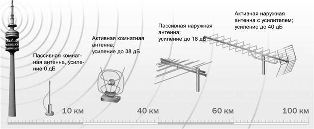
The modern market offers a huge range of antennas for reception terrestrial television. There are two main types of these products that allow you to receive meter and decimeter radio waves. They can also be divided according to the place of use into outdoor and indoor. Fundamentally, they are not much different. Here, first of all, the emphasis is on size and maintaining the necessary parameters under the influence of weather conditions. In this article we will discuss existing types of these products, consider what parameters they have, and how to conduct testing. And for those who like to tinker, we’ll tell you how to make a decimeter antenna with your own hands.
What's the difference?
Let's try to explain in a nutshell how to determine what type of product is in front of you. The UHF antenna looks like a ladder. Install them parallel to the ground. Meter ones are crossed aluminum tubes. Appearance both types are shown in the photo below. There are also combined antennas, when both the “ladder” and cross tubes are combined.
The problem of choice
It would seem that everything is simple. However, the buyer is faced with the question of how to choose the right device and what parameters to pay attention to. In general, it is best to test TV antennas directly in the conditions in which they will operate. The passage of a radio signal is often individual for a particular area. Thus, a product shows the same results in laboratory conditions, but completely different results in the field. There are certain tactics that allow you to test both meter and decimeter TV antennas. However, when choosing such a product in a store, we do not have the opportunity to conduct full testing. No seller will agree to give us several different antennas to test. In this case, you have to trust the characteristics of these products. And hope that the selected antenna will perform its functions according to the passport data, and not real conditions.

Basic parameters
A decimeter antenna is characterized primarily by its radiation pattern. The main parameters of this characteristic are the level of the side (auxiliary) lobes and the width of the main lobe. The width of the diagram is determined in the horizontal and vertical planes at a level of 0.707 from highest value. So, according to this parameter (the width of the main lobe), diagrams are usually divided into non-directional and directional. What does this mean? If the main lobe has a narrow shape, then the antenna (decimeter) is directional. Next important parameter is noise immunity. This characteristic primarily depends on the level of the back and side lobes of the diagram. It is determined by the ratio of the power released by the antenna, subject to a consistent load at the time of receiving a signal from the main direction, to the power (with the same load) when receiving from the side and rear directions. First of all, the shape of the diagram depends on the number of directors and the design of the antenna.
What does the term “wave channel” mean?
TV antennas of this type are very effective directional receivers of radio signals. They are widely used in areas of clearly weak television airwaves. The antenna (decimeter) of the “wave channel” type has high gain and has good directivity. In addition, these products have relatively small dimensions, which (along with the high level of gain) makes it very popular among residents of holiday villages and other settlements, distant from the center. This antenna also has a second name - Uda-Yagi (named after the Japanese inventors who patented this device).

Operating principle
A decimeter antenna of the “wave channel” type is a set of elements: passive (reflector) and active (vibrator), as well as several directors, which are installed on a common boom. The principle of its operation is as follows. The vibrator has a certain length, it is located in the electromagnetic field of the radio signal and resonates at the frequency of the received signal. In it, an electromagnetic field is induced on each passive element, which also leads to the occurrence of EMF. As a result, they re-emit secondary electromagnetic fields. In turn, these fields induce additional EMF on the vibrator. Therefore, the dimensions of the passive elements, as well as their distances from the active vibrator, are chosen such that the EMF induced by them due to secondary fields is in phase with the main EMF, which is induced in it by the primary electromagnetic field. In this case, all EMFs are summed up, which increases the efficiency of the design compared to a single vibrator. Thus, even an ordinary room can provide stable signal reception.
The reflector (passive element) is installed behind the vibrator 0.15-0.2 λ 0. Its length should exceed the length of the active element by 5-15 percent. Such an antenna produces a one-way directional pattern in the vertical and horizontal planes. As a result, the reception of reflected signals and fields that come from the back of the antenna is significantly reduced. If it is necessary to receive a television signal over long distances, as well as in difficult conditions, in the presence of a lot of interference, it is recommended to use a three or more element antenna, which consists of an active vibrator, one or more directors and a reflector.

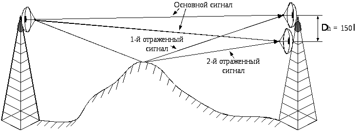
Direct and reflected signals
In an article devoted to a wave receiving device (“Tele-Sputnik” No. 11 for 1998), it was noted that in the case when the signal source is not a standard (that is, not laboratory) generator and emitting antenna, and the signal is broadcast by a television tower, a significant Weather conditions play a role, as does the location where the receiver is installed. This especially affects the operation of UHF products. This is explained by the fact that in the decimeter range there is less, and therefore, obstacle avoidance is much worse, and any signal reflections play an important role in the quality of the received picture. In particular, even the wall of a house can be a wave reflector. So, in conditions where there is no direct visibility, this property can be used - to receive the reflected signal. However, its quality will be lower than that of the direct one. If the level of the broadcast signal is high, but there is no line of sight, then you can use the reflected wave. In fact, an indoor decimeter antenna works precisely on this principle. After all, it is difficult to catch a direct wave in a room if the windows face the opposite direction. Therefore, if you try, you can always find a point where the received signal will be higher. But in the case of direct visibility, any reflected interference will spoil the received picture.
A technique that allows you to compare antenna parameters
In order to test receiving devices, they need to create the same conditions:
1. Select the installation location where your antenna will operate. You can use a balcony, roof or mast. The main thing is that both the height and the location are the same for all products.
2. The direction to the source of the broadcast signal should be maintained with an accuracy of three degrees. To do this, you can make a special mark on the mounting pipe.
3. Measurements should be carried out under the same weather conditions.
4. The cable connecting the antenna and the TV must have the same resistance and length. It is best to use one wire, changing only the receivers.
Testing should be carried out only for products of one type. For example, an indoor UHF antenna should not be compared with an outdoor one or with meter receivers. It should be understood that field tests may produce results that differ significantly from laboratory tests.

UHF antenna for digital television
Recently, the media have been increasingly talking about the need to switch to digital television. Many have already done this, and some are still thinking about it. So far, the signal is broadcast in both modes. However, the quality leaves much to be desired. In this regard, people are interested in what decimeter antennas can be used for T2. Let's look at this issue. Essentially, digital television broadcasts on a UHF channel. So a standard UHF antenna may be suitable for receiving it. In stores you can often see receivers that indicate that they are intended for digital television. However, this is a marketing ploy that allows you to sell a standard decimeter antenna for more than it costs. When purchasing such a product, you will not have a guarantee that it will provide better reception than what is already in your home and has been working for more than one year. As we said earlier, the quality depends mainly on the level of the broadcast signal and line of sight conditions. However, it should be borne in mind that in most cities, significantly more powerful generators are used for transmitting digital television than for analogue. This is done in order to speed up the transition to new standard. After all, viewers want to see a clear image, and not “snow” on the screens. Therefore, if there is a receiver in the window that says “UHF antenna for DVB T2”, know: this does not mean that this is some kind of special product. It’s just that a not entirely honest seller wants to profit from an uninformed buyer. You should also know that the transition program to the new standard provides for the creation of advisory centers. In them you can get comprehensive information on any issue related to digital television. All consultations are provided free of charge. In some cities, this equipment is in test mode, so the signal may be unstable or weakened. Don’t worry, the center staff will always tell you how to solve the problem with signal reception quality.

DIY decimeter antenna
The length of UHF waves falls within the range from 10 cm to 1 m. Their name comes from this feature. At this frequency they propagate predominantly in a straight line. They practically do not bend around obstacles and are only partially reflected by the troposphere. In this regard, long-distance communication in the UHF range is very difficult. Its radius does not exceed one hundred kilometers. Let's look at a couple of examples of how to make a decimeter antenna at home.
First option homemade receiver television broadcasting will, so to speak, be assembled on the knee from scrap materials. UHF channels are located in the range from 300 MHz to 3 GHz. Our task is to produce an antenna that will operate precisely at these frequencies. For this we need two 0.5 liter beer cans. If you use a larger capacity, the received frequency will decrease. For installation you will need some kind of frame; you can use a board 10 cm wide. You can also use a regular wooden hanger, in which case the resulting antenna can be hung on a nail in any convenient place in the room. In addition to the frame and cans, you need to prepare a pair of self-tapping screws, tools, a coaxial cable, a connector, terminals, and insulating tape. We put a television connector on one end of the cable and solder it. We insert the second end into the terminal block. Next, we attach the terminals to the necks of the cans with screws. The wires should fit snugly to the metal. Now let's start assembling the antenna itself. To do this, we secure the jars on a horizontal crossbar with their necks facing towards each other. The distance between them should be 75 mm. You can use insulating tape to secure the cans. That's it, the antenna is ready! Now we need to find a place for stable reception of a television signal and hang our “hanger” in this place.

Receiver for digital television
This section is intended for people who do not want to use a regular (analog) product, but want a special UHF antenna to be used for the new format. It is also easy to assemble such a receiving device with your own hands. To do this, we will need a square wooden (or plexiglass) frame with a diagonal of 200 mm and regular cable RK-75. The option presented to your attention is a zigzag antenna. It has proven itself well when working in the digital television reception range. Moreover, it can be used in places where there is no direct visibility to the signal source. If your broadcast is weak, you can connect an amplifier to it. So let's get to work. We strip the end of the cable by 20 mm. Next, we bend the wire into a square shape with a diagonal of 175 mm. We bend the end outward at an angle of 45 degrees, and bend the second stripped end to it. We connect the screens tightly. The stripped central core hangs freely in the air. On the opposite corner of the square, carefully remove the insulation and screen over a 200 mm area. This will be the top of our antenna. Now we connect the resulting square with a wooden frame. At the bottom, where the two ends are connected, copper staples made from thick wire should be used. This will ensure better electrical contact. That's all, the decimeter antenna for digital television is ready. If it will be installed outside, you can make a plastic case for it, which will protect the device from precipitation.
A very simple, reliable indoor active antenna for digital TV made from affordable components and materials.
The choice of antenna for viewing digital channels depends entirely on the quality of the television signal in a particular place, exactly where TV programs will be watched, and depends not so much on the distance to the repeater (although this, of course, is important), as on the reception conditions in a particular place , and this is already individual.
In some places it will work with a piece of wire, but in others an external active antenna does not always help.
There is no universal solution, but there are also priorities in the search for it - such as an active antenna.
The television signal received by an active antenna is more stable (does not depend on the weather, time of day, etc.), and for most cases such an antenna is quite sufficient.

The cost of the described antenna, in comparison with similar antennas on sale with the same characteristics, is at least three times cheaper, and if the amplifier (the heart of such an antenna) fails, there are no problems with replacing it.
The power supply for the antenna amplifier is in a wide range - from 2.5 to 14V (measured with an 838 multimeter, on a 555 amplifier), and can be supplied either directly from a digital set-top box through the antenna socket, or from an external source (USB, AC power supply, vehicle on-board network) through the power injector.

Material and components for making the antenna:
Antenna amplifier from the “dryer” (I prefer in this design - 555, 777, 2000) - 1 pc.

Wire or tube - aluminum, copper (not critical) Ø 3 - 5 mm. (also not critical) with a length of at least 600 mm.

You can use a SAV 1 electrical installation wire of suitable diameter (aluminum, single-core), removing the insulation only at the ends to make contacts.

A set of hardware consisting of two M3 × 10 mm screws, two M3 nuts, and four wide-flange washers.

Coaxial (antenna) cable RK 75-3 (any convenient, thin, soft, with an amplifier, 50-ohm is possible).

TV antenna plug (any).

If a mains power injector is used, the plug is not needed.

Antenna manufacturing:
The design of the antenna is primitive and quite understandable even from a photograph.

Having cut a length of 600 mm from the wire (tube), you need to bend the ring (make a vibrator), and flatten the ends and drill holes Ø 3 mm in them.

Clean the television cable, connect the antenna amplifier on one side and the plug or injector on the other, carefully ensuring that there is no short circuit between the braid and the central core of the coaxial cable.


Having collected everything together, connect it to the set-top box or via an injector directly to a TV with a DVB T-2 tuner.

By going to MENU, manual setting, install a channel for digital reception in a given area, and by turning on the power of the antenna (in the MENU for TV set-top boxes) or through the injector (for a TV with a DVB T-2 tuner), find the place of best reception for the antenna, focusing on the “signal quality” scale on TV screen.
More details in the video on my YouTube channel.


It works great in the form described, but if someone wants to design it more respectably, they just need to select or make a suitable case (a flat, rectangular box 15 - 20 mm thick, about 200 mm long and about 100 mm wide).
In this case, the vibrator can be made from a piece of any thin coaxial cable, a length equal to the perimeter of the box and soldered with a stripped braid directly to the contacts antenna amplifier, and laid along the inner perimeter of the selected body.
Today, terrestrial television is the most common among users. It works by collecting radiation from the broadcaster to the receiver. Due to a number of factors, the antenna may fail, and install a new one in at the moment not possible.
In this case, you can make a homemade antenna for digital television, which will receive a television signal no worse than factory devices. This article will discuss the manufacture different types antennas for digital TV with your own hands for specific conditions, for temporary and permanent use.
Types of receiving antennas
TV antenna is a dipolar device that can emit and receive a signal in a specific frequency range.
Today, several types of devices are common for television:- Meter wave range (MV antenna, VHF). Designed to receive terrestrial analogue broadcasting, which occurs in the frequency range 1 - 300 MHz.
- UHF wavelength (UHF antenna, UHF). They receive shorter wavelengths of radiation that transmit signals at frequencies of 0.3 - 3 GHz.
Today, DVB digital television broadcasts in the UHF range.
- Terrestrial television (DVB-T2). It works by transmitting a signal from a broadcaster to a receiver via terrestrial repeaters. The signal is emitted at frequencies of 314 - 898 MHz.
- Satellite TV(DVB-C2). Broadcast at ultra-high frequencies from 1 GHz.
From the operating ranges discussed above, we can conclude that for a simple digital television antenna there is a minimum and maximum length waves it can take. This means that before assembling an antenna with your own hands for digital television, you will need to calculate it.
Calculation
Depending on the design, you can make an all-wave antenna yourself or one that operates in a specific frequency range. There is one fundamental difference between them - all-wave devices are not capable of receiving weak signal, especially drowned out by the background of stronger radiation. Other homemade antennas do not cover all digital broadcast frequencies.
In order to correctly make a working antenna for digital TV, you need to approach its calculation responsibly for one more reason - in practice it is impossible to check the quality of reception digital signal.
If, at a low signal level, analog television works with interference, but shows, then there is no image in digital and it is not clear whether the problem is in the device or in another (cable, weak reception signal). In this case, development work with the antenna already turned on will not work.
Modern Smart TVs and receivers display the level of the signal recorded at the receiver, but most conventional digital devices this function do not support. It is impossible to make even a simple decimeter antenna yourself without calculations, unless it is all-wave.
Calculation rules
Digital TV broadcasts from different multiplexes at different frequencies, which correspond to different wavelengths. To receive a high-quality signal, the emitted wave must completely “lie” on the active area of the receiver.
Therefore, calculating an antenna for digital television with your own hands must be done according to the following scheme:- calculate the DVB-T2 wavelength for the antenna, emitted during broadcasting of each multiplex;
- select the longest wave;
- calculate the half-length of the wave cross section, because it is projected perpendicularly onto the receiver.
Below we will consider the procedure for calculating the active area for a digital antenna with your own hands, and as an example we will take the calculation of the broadcast frequency in Moscow.
Case Study

- 1st multiplex (32 TVC, 546 MHz);
- 2nd multiplex (24 TVC, 498 MHz);
- 3rd multiplex (34 TVC, 578 MHz).
The wavelength is calculated using the formula ƛ = 300/F, where F is the frequency in megahertz (MHz). As a result, each multiplex sends a wave:
- ƛ1 = 300/546 = 0.55 m;
- ƛ2 = 300/498 = 0.60 m;
- ƛ3 = 300/578 = 0.52 m.
It turns out that the repeaters of the second multiplex of Moscow television emit a wave of the greatest length, which will later be used for calculations.
Important! For ease of calculation, the resulting value can be rounded, but only up!
The only thing left to do is to calculate the length of the active region of the future receiver, which will receive the signal. Because the emitted wave has a sinusoidal shape, then its cross section will be ½ of the length, and its half-length - ¼. The total is 0.60/4 = 0.15 m = 15 cm for digital television.
Advice! The calculation is shown for all multiplexes as an example, but it can be simplified by calculating the value for only one channel package. Radiation of a lower frequency will always have the longest electromagnetic wavelength.
Location and connection
When the theoretical calculations have been made, all that remains is to plan the future structure for assembly with your own hands.
There are two planning issues to consider:- location
- connection .
- You can make a home or outdoor antenna with your own hands. The latter can be a simple unidirectional television receiver, which is not interfered with by signal-attenuating obstacles (house walls, other buildings).
Also, an outdoor digital antenna can be installed on the roof, which will significantly improve the quality of the received signal. It should be directed to a digital television repeater.
- For installation outdoors, and especially on the roof, a long cable is required. It causes natural signal scattering (noise) and the longer its length, the weaker the signal level reaches the TV.
To make an antenna for digital television with your own hands that will work effectively, you will need to find a compromise between these factors.
In densely built areas or sparsely populated areas with a large distance from the television repeater, the digital antenna will have to be taken outside. In other cases, an indoor receiver also works effectively.
Advice! There is no clear rule for choosing a placement; each case is unique. The best indicator of a reliable installation is neighboring houses. If there are a lot of outdoor devices for receiving television, then make one. In an area of super-dense buildings, you need to look at the roofs of multi-storey buildings.
A small number of receivers does not indicate anything (sometimes, for greater confidence, residents install them even in conditions of good reception by room devices). Only if there are many antennas, and among them there are collective ones, installation on the roof will be required.
Manufacturing
When the calculation has been completed and the type of future receiver for terrestrial television has been selected, you can begin the main assembly work. It is worth noting that you cannot make a DVB-T2 digital TV antenna with your own hands, the design of which is suitable for all cases. Therefore, several types will be considered homemade devices for specific tasks.
From beer cans

An important advantage of such an antenna for television is its quick production from available materials. The whole process will take no more than 15 minutes. It is easy to assemble such an antenna, but for efficient work You will need a high-quality signal and the absence of obstacles. It is suitable for residents of small cities and suburban areas.
For assembly you will need the following parts and tools:- 2 beer cans;
- bolts and screws with a screwdriver;
- 2 wooden sticks;
- a piece of copper wire;
- electrical tape or tape;
- antenna plug and cable.
The device requires a T-shaped or cross-shaped frame. It is made of wood.
Then comes the main manufacturing process according to the following scheme:
- Make a hole for the bolts in the middle of the bottoms of the cans. You can use scissors or a self-tapping screw.
- Remove the insulating coating from the cable to a length of three cans + 20 cm. the outer contour is not touched.
- Place the cans parallel with their necks facing each other and pull the cable through one hole to the other. It must be secured at the end with a self-tapping screw or bolt.
- Secure the cable coming out of the hole and its exposed area between the cans with wire.. The connection point is required, otherwise there will be a lot of noise in the cable and the image will not appear on the screen.
- Banks fix one roll of adhesive tape or electrical tape to the horizontal frame bar.
- Connect the plug to the cable.
Attention! You need to work carefully with cables on bends! Only a solid external circuit effectively suppresses noise in it, and if it is damaged, the transported signal will be greatly attenuated. There is no need to try to “save” the exposed part of the cable; for this there is a margin of 20 cm.

The ethereal antenna from beer cans has already been assembled, all that remains is to determine the optimal distance between the cans. To do this, you need to connect the plug to the antenna and move the cans along the bar (bringing them closer and further away from each other) until a good signal is caught. In most cases, 6 - 7 cm is sufficient.
When the optimal location of the cans is found, they need to be firmly secured to the circuit.
For outdoor use, it is recommended to cover the homemade television structure with polyethylene or make a special plastic frame. It is better to use a hook as fasteners and hang the structure. If there is a significant length of exposed cable left at the exit from the hole, it must be wrapped with electrical tape, leaving no more than 2 cm.
Figure 8

For digital TV, a homemade figure-of-eight antenna is popular, which is also called a biquadrat or Kharchenko antenna. Externally, its active region is represented by a double diamond-shaped square. This homemade design works successfully in almost any conditions, with the exception of ultra-dense buildings, because unable to receive the reflected signal.
For the “eight”, a calculation by wavelength will be required and each side of the square must correspond to the half-length of the wave’s cross-section, therefore, its perimeter is equal to the length of the wave itself. For Moscow DTV, the side and perimeter will be 15 and 60 cm, respectively.
The material for making the antenna can be copper 2-3 mm or aluminum wire 5 - 6 mm. In total, you need to make two squares. You need to cut 2 cm from the ends of the wires and connect them together so that you end up with a single structure of two squares with a common angle.
Important! The connected pairs of wire ends must be insulated from each other, otherwise the device will only be a signal emitter!
A beam can be used as a frame. The receiver can be immediately secured without preliminary fixation, because The antenna is made according to calculation and practical experiment with the signal is not required. The cable must be soldered in the middle to one of the points where the ends of the wires connect.
Double-triple square
The antenna is manufactured with the same calculations as a biquad device. The general design is represented by several squares of identical parameters, located one after the other. Unlike the G8, it is not capable of receiving a good signal from a very distant television repeater.
The purpose of a double or triple square is to receive a signal in conditions of strong background radiation. In an area of super-dense development, it often happens that a DTV tower is nearby, but besides it there are other stations of different frequencies, against the background of whose radiation the decimeter wave remains “in the shadow”.
Double-triple is a homemade digital television antenna for receiving a specific wavelength, and the multi-level antenna design acts as an amplifier.
The squares can be installed on any block, and a thick conductive element can be used as a tripod (legs) for vertical mounting.
Important! The squares can be connected to each other only by outgoing conductive elements, i.e. not in the active region section. If this is not possible, you can strip the cable to a greater length and solder it to the lower corner of each square, and then fasten the structure to the block.
After assembling several squares, you need to fix them and experiment with the distance between them until a good signal is caught, and then fix them.
From a cardboard box

To be more precise, the box serves as the source material for a DIY digital television antenna. From it you need to cut two flat rectangles 25x30 cm.
In addition to it, you will need the following materials and tools:- food or household foil paper;
- glue (any kind, you can use stationery);
- copper wire;
- pair of bolts and nuts;
- screwdriver and scalper(or razor blade);
- TV cable with plug.
The first step is to cut out two squares from foil with a perimeter similar to that of cardboard blanks. Then glue them tightly to the cardboard. Remove residual adhesive material from the foil.
Important! You need to be patient and carefully place the foil on the cardboard. Gaps and protrusions must be excluded, otherwise good quality of the received signal is not guaranteed!
The finished foil squares will serve as an active signal-receiving area; you just need to connect the cable. To do this, using a blade or scalper, carefully cut holes for the bolts at the corners of adjacent sides of the squares.
The design is ready, but again it is necessary to determine the optimal distance between the squares. To do this, you need to connect the cable to the TV and move the squares apart so that adjacent sides remain parallel.
After finding the required distance, fasten the squares to the frame. Adjacent corners that are opposite to the contacts can be used as the fastening area. The DIY antenna is ready for use.
Butterfly

By design, it consists of a series of vertically located antennae and externally resembles Polish (whip) factory digital television antennas. The only difference is the absence of a phased array, instead of which a frame will be used.
To make it you will need the following materials:- wooden stick;
- protractor and ruler;
- aluminum wire 5-6 mm(3 meters);
- 16 bolts with nuts or soldering iron;
- screws or drill;
- wire cutters
All Polish digital television antennas are outdoor, therefore, this design will also be used only for outdoor installation. Long antennae will be vulnerable to a strong meter, so it will not be possible to use 2-3 mm copper wire and only a thicker aluminum analogue is more practical.
For reference: DTV programs work with 21 TVCs ( physical channel television), which corresponds to a frequency of 314 MHz. The wavelength will be 300/474 = 0.633 m ~ 64 cm. This is the maximum value emitted by RTRS repeaters. Consequently, the length of the active area will be 16 cm, and for all the “antennae” it will require 256 cm. Therefore, 3 meters of wire will be enough. The stick will serve as a frame; its length must be at least 60 cm. Markings for “antennae” must be made on it in the following way:- mark 4 points at the same distance from each other 18 - 20 cm;
- from each point draw lines perpendicular to the frame, but parallel to each other;
- From straight lines, measure 4 adjacent angles of 30°(two on the left and on the right) and put dots;
- draw lines from the central to the marked points at an angle.
The result should be the same markings as shown in the antenna diagram in the figure below. The angled lines will serve as a guide for the placement of the antennae.
For the Moscow region, the half-length of the wave cross-section is 15 cm.
Based on this value, we will consider two ways to make a butterfly-shaped antenna with your own hands.Using a soldering iron
When using it, the process is significantly reduced. It is necessary to attach a metal product in parallel to the wooden stick. These can be 4 pieces of steel (which then need to be connected) or wire. The conductive element should not cover the wooden frame so that the markings are visible.
The central points on the markings are the places where the antennae are soldered, and the lines at an angle are the places where they are placed. You need to use wire cutters to cut 16 pieces of antennae from the wire. homemade antenna digital TV measuring 15 cm, and solder 4 antennae to each point. For reliability, it is better to wrap each group of antennae with electrical tape.
With bolts
There is no need to add metal to the wood, and the overall structure will be much lighter. The stick itself should be 4 cm wide and 2 cm thick.
First you need to make “dimples” for the antennae using a drill or self-tapping screw, the thickness of which will be the same as theirs. They are performed from the side of the stick inward in the direction of the line at an angle on the marking. Then you need to make through holes that will go through the dimples tangentially. The frame is ready.
In this case, pieces of wire are cut off with a margin of 17 cm. The finished antennae are inserted into the dimples 2 cm deep, after which they are tightly fixed with a bolt and nut. Upon completion, wrap the antennae with thin wire and connect them together.
The result is a more reliable and practical design than soldering, but it will take much longer to assemble.
From coaxial cable

Sometimes it happens that the antenna comes out at the most unexpected moment and a football match or an important premiere is about to start. It’s easy to find tools in the city to assemble a homemade receiver; in extreme cases, you can buy it or ask a neighbor.
When a digital antenna breaks down at the dacha or at grandma’s in the village, you may not even have an ordinary screwdriver at hand, and you can forget about the soldering iron. And in this situation, a rather primitive cable antenna for digital TV, assembled in 5 minutes, comes to the rescue. This is the simplest do-it-yourself receiving device.
The television cable itself is used as the active region, which easily receives analog and digital TV. The popular name for such an antenna is “Loop”.
The assembly is performed as follows:
- the cable is disconnected from the faulty digital television receiving device;
- the end of the antenna wire is stripped of insulation;
- measure 40 cm and carefully remove 2 cm of insulation from the section(it is important not to damage the outer contour);
- the bare area and the section stripped of insulation are applied parallel to each other and firmly connected with wire.
The result will be a circle of cable with a diameter of slightly more than 15 cm, which will serve as a receiver. Now in the middle (on the opposite side from the connection point) you need to measure 4 cm and remove the insulation. A DIY device for digital television made from coaxial cable is ready.
Such a receiver will be noisy due to the open end of the cable, so it is not suitable for continuous use. Analogue television programs are always shown with interference, but the picture quality is satisfactory.
Gradually, everyone is abandoning analogue television, giving preference to digital broadcasting. Largest providers They are also restructuring to work with a newer, modern format. The era of analogue TV is gradually coming to an end.
In order for previously installed home antenna devices to complete their resource, it is enough to connect a DVB-T receiver to the TV, as a result, digital signals will be received correctly.
You can make an antenna for digital television with your own hands, so there is absolutely no need to go to the store and spend extra money. You don’t need any special skills or equipment; you can create the necessary design using available tools.
Now we will answer in detail the question of how to make an antenna for digital TV. We will carefully analyze the process, select the optimal material, and also carry out all the necessary calculations. Nevertheless, first we will deal with the theoretical nuances.
Regardless of the signal format, it is transmitted from the tower emitters. Reception of the wave channel is provided by the antenna device. To receive a digital signal, you will need a sinusoidal device with the highest possible frequency, which is measured in MHz.
When an electromagnetic wave passes through the surface of the receiving beams of the antenna, a V-voltage is induced in it. Each wave contributes to the formation of a different potential, marking it with its characteristic sign.

Under the influence of an induced voltage, an electrical current flows in a closed receiving circuit with resistance R. It is gradually growing. Processing is carried out by the TV circuit, the picture is displayed on the monitor, and the sound is broadcast through the speakers.
You won't be able to connect digital broadcasting using a regular indoor antenna. Firstly, you will need an intermediate link that will provide decoding of information - a DVB-T receiver. Secondly, you should use a UHF antenna or Turkin antenna for DVB.

Antenna figure eight
How to make such an antenna with your own hands? First you need to prepare the material. Then carry out the appropriate calculations. At the final stage, assemble the structure and connect it to the TV. Nothing complicated. Every user can cope with this task.

Materials for antenna assembly
Making an antenna for digital television is not difficult. The list of materials used will vary depending on the type of antenna device. For example, if you wish, you can make it even from the most ordinary beer cans.
To produce a good and simple TV antenna for digital channels, you will need copper or aluminum wire with a thickness of 2 to 5 millimeters. In general, it will take only 1 hour to create such a design. You also need to use:
- handset;
- corner;
- copper or aluminum strip.
You will definitely need a tool that will allow you to bend the frames to the required shape. To bend the wire, use a hammer after securing the material in a vice.

You can make your own antenna not only from wire, but also from cable (coaxial). Choose a plug that matches the connector on your TV. Naturally, you also need to fix the structure; the bracket is made from scrap materials.
As for the cable, it must be taken with a resistance in the range of 50-75 Ohms. Particular attention should be paid to insulation if the device will be placed outdoors.
The specifics of fastening are determined in accordance with where the structure will be located. For example, residents of multi-storey buildings will be able to make their own antenna for digital TV and hang it like a home antenna, i.e. on the curtains. To do this, you will need large pins that will serve as a fastening element.

However, if you want to place the created device on the roof, then you need to make a bracket. To do this you will need a file, a soldering iron and a needle file.
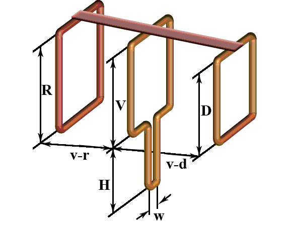
We've sorted out the spiral antenna, but you can also make another design - a double square. It is made from copper, brass or aluminum tubes. Wire 3-6 mm thick is less commonly used. In general, the choice of material is determined in accordance with the MF band and the number of channels.

Double square - two frames that are connected by an upper and lower arrow. The small frame is a vibrator, and the large one is a reflector. To achieve maximum gain, increase the number of frames to three. The third square is the director.
The mast must be made of wood. At least its upper part. Please note that it should start at a distance of one and a half meters from the level of the frames.
So, step by step instructions:
- Take the coaxial cable and strip it from both ends.
- One end will be attached to the antenna, the wire should stick out 2 cm.
- The screen and braid are twisted into a bundle.
- We get two conductors.
- Solder the plug to the second edge of the cable. A distance of 1 cm is sufficient. If you use a crimped metal plug, you can skip further steps.
- Tin and make 2 more conductors.
- Wipe the solder joints of the plug with alcohol.
- Place the plastic part of the plug onto the wire.
- A single core is soldered to the central input of the plug.
- A multi-core harness is soldered to the side entrance of the plug.
- Crimp the grip around the insulation.
- Screw on the plastic tip or fill it with glue.
Calculation
To set up digital television reception, it is absolutely not necessary to calculate the wavelength. Just try to make a broadband design. As a result, you will be able to take maximum quantity signals. To achieve this result, add additional elements to the T2 antenna with your own hands. It is about them that will be discussed further.

The calculation of an antenna for digital TV is based on determining the signal transmission wave. Divide this value by 4 to get the required side of the square. To determine the distance between the two components of the device, make the outer sides of the rhombuses a little longer, therefore, the inner sides, on the contrary, should be shorter.
If you don’t want to calculate the dimensions of the antenna yourself, use ready-made drawings:
- The inner side of the rectangle is 13 cm.
- The outer side of the rectangle is 14 cm.
The difference is the distance between the squares; by the way, they should not be connected under any circumstances; the extreme sections provide the necessary maneuver for folding the loop. It is to this that the coaxial antenna wire is attached.
Antenna manufacturing
If we calculate the entire length, we will end up with a value of 112 centimeters. Cut the wire or any other material that you plan to use, take a ruler and pliers, and begin to bend the structure. The angle should be 90 degrees. If the sides do not match in length, it’s okay, a small error is acceptable.

Initial data for making an antenna for digital TV:
- The first element is 13 centimeters and 1 centimeter per loop, by the way, it can be bent right away.
- Two elements of 14 centimeters each.
- Two are 13 centimeters each, but there must be a turn in the opposite direction; here a bend is created to another square.
- Two more sections of 14 centimeters each.
- The last one is identical to the first one.
The antenna frame for digital TV is ready. If you did everything correctly, then between the 2 halves there is a gap of several centimeters in the middle. Naturally, there may be minor differences. After this, the loops and bend areas must be cleaned until no metal is visible. Processing is carried out with fine-grain sandpaper. We connect the loops and crimp them with pliers to fix their position.
The design itself is ready, but in order for the antenna made for T2 to function correctly, the cable must be processed. We start with double-sided stripping of the wire. One edge will connect directly to the antenna. You need to strip the cable in this area so that the cord sticks out about two centimeters. If you get a little more, you can simply cut off the rest later.

We twist the screen and cable braid into a bundle, as a result we get 2 conductors - a central core and a twisted element of several braided wires. All this needs to be tinned.
By using soldering station Solder the plug to the second edge of the cable. A centimeter length is quite enough, small errors are acceptable. According to the principle described earlier, you need to make a pair of conductors and tin them.
The plug is placed in those areas where soldering will be carried out in the future; first wipe it with alcohol or a special solvent. Then, using a file or emery, we clean it. Place the plastic plug element onto the cord. Now start soldering. Attach a core to the central entrance, and a multi-core braid to the side entrance. Crimp the grip around the insulation.

Screw on the plastic tip; some experts even fill it with glue or a special sealant to strengthen the fixation. While the fixing base is still wet, quickly assemble the plug by screwing on the plastic part, and then remove excess glue or sealant. As a result, it will be possible to maximize the service life of the plug. The homemade product has been created, it's time to connect it.
Connection
Connect the cable and the homemade frame DVB antennas T2. It is absolutely not necessary to bind to any specific channel, so solder the cord in the middle. As a result, a broadband antenna will be created that will receive the maximum number of TV channels. Solder the second split end of the wire to the other two sides again in the middle, previously you stripped them and also tinned them. To extend the reception range, do not solder the cable from the bottom.
When the structure is assembled, it must be checked. We connect the tuner and turn on the TV. If digital television receives, for example, you managed to set up 20 channels, you need to finally complete the assembly. Fill the areas where soldering was carried out with sealant.

However, if there are very few active channels or there is some interference, then you need to find a place where there will be an optimal signal. If there are no positive changes, change the antenna cable. To simplify the testing process as much as possible, use telephone wire, it is quite cheap. Solder the plug and frames to it. If the signal quality has improved, then the problem is really in the cable. Digital set-top box will broadcast channels even if noodles are used, but as practice shows, its service life is extremely limited.
To protect the cable connection areas and antenna frames from precipitation and other atmospheric influences, wrap the solder joints with ordinary insulating tape. However, this is not a permanent solution. A more effective option is to install heat-shrinkable tubing on the soldering areas, which will ensure proper insulation.

An alternative option with maximum reliability is glue or sealant. The fact is that these substances do not conduct current. Be sure to make a housing for the antenna; an ordinary plastic cover will do for this. If necessary, make indentations so that the frame “settles down”; do not forget about the cord outlet. Pour in the sealant and wait for it to dry. Everything is ready, we connect the equipment and enjoy digital TV.
Double or triple square for weaker signal
The TV antenna is used in villages, dachas and in areas that are located on the border of the coverage area of television towers. The device allows you to receive even a very weak signal. If you do everything correctly, the power of the TV signal will increase noticeably.
A double or triple square has only one drawback - you need to direct the structure to the signal source with maximum accuracy. Therefore, if you do not know where exactly the tower is, difficulties will arise.

The number of frames determines the quality of the signal. Therefore, if you are outside the coverage area, you don’t have to limit yourself to 2-3 frames, you can make 5. Do not open the antenna with varnish or paint it. This negatively affects the quality of signal reception.
What are the strengths of the design? First of all, the quality of reception. Even if you are far from the repeater, the signal will be clear. However, it will be possible to achieve a positive result only if the user correctly determines the dimensions of the frames and matching device.
Materials
To make an antenna for digital TV yourself, you need to prepare materials that will later be used to make the structure. The antenna is made from metal tubes or wire:
- 1-5 meter channel - copper, brass, aluminum tubes 10-20 millimeters thick;
- 6-12 meter channel channel - copper, brass, aluminum tubes 8-15 millimeters thick;
- decimeter range - copper, brass wire with a thickness of 3 to 5 millimeters.

Double square - 2 frames, which are connected by a pair of arrows (upper and lower). The smallest frame is the so-called vibrator, and the largest is the reflector. A device with three frames will have a higher TV signal gain. The third square is usually called the director.
Instructions for creating a T2 antenna:
- The top arrow (made of metal) must connect the middles of all frames.
- The lower boom is made using electrically insulating materials: wood, textolite.
- Arrange all the frames so that their centers are on the same line.
- The direct line should be sent to the repeater.
- The vibrator must be open circuit. Its edges are fixed to a PCB plate.
- If you made frames from metal tubes, then the edges should be flattened and holes should be made in them to fix the lower boom.
- The mast must be made of wood, or at least its upper part.

Size calculation
The calculation of an antenna for digital TV will directly depend on the range - meter or decimeter. The dimensions of the antenna with three frames are characterized by a large distance between the ends of the vibrator. You need to leave more distance - 50 millimeters.

The tables show the sizes of two-element loop antennas. Meter range:
|
Channel numbers |
||||||||||||
UHF:
Size of three-element antennas. Meter range:
|
Channel numbers |
||||||||||||
UHF:
Vibrator connection
Considering the fact that the frame is symmetrical, and the connection is made to an asymmetrical antenna cable, you need to use a matching device. The best option– short-circuited loop. It is made from pieces of coaxial cable. The left segment is a feeder, and the right one is usually called a train. In the place where the feeder and cable will be connected, we fix the cable, which is subsequently connected to the TV.
What should be the length of these segments? The calculation is carried out in accordance with the wavelength of the received TV signal.

At one end you need to cut the cable, removing the aluminum screen. The braid must be twisted into a tight rope. We cut off the central conductor down to the insulation. The feeder also needs to be cut. Remove the screen, made of aluminum, and then twist the braid. However, we leave the central conductor.
The further assembly process is carried out as follows:
- Solder the cable braid and feeder conductor to the left edge of the vibrator.
- The feeder braid needs to be soldered to the right edge of the vibrator.
- A metal jumper connects the cable braid to the lower end of the feeder. These elements can also be fastened with metal wire. The main thing is that there is proper contact with the braid.
- The braid determines not only the electrical connection, but also the distance between the sections of the matching device.
- If there is no metal wire and jumper, then twist the braided lower part of the cable into a bundle, after first removing the screen and removing the insulation. To ensure proper contact, you need to solder the wire harnesses using solder that melts easily.
- The cable pieces should be parallel to each other. Distance – 50 millimeters (small error is acceptable). To secure the distance, special clamps made of electrical insulating materials are used. You can also attach the matching device to the textolite plate.
- The cable that is inserted into the TV socket should be soldered to the feeder (to the bottom). The braids are connected to each other, like the central conductors.
To reduce the number of connecting elements, the feeder and cable connected to the TV can be made one. Remove the insulation where the feeder ends. This is done in order to install the jumper.

A matching device is a mandatory element that helps prevent interference. It will be especially useful if the signal transmitter (TV tower) is located at a great distance.
Butterfly antenna
The TV antenna can also be made in the shape of a butterfly. Such a device will be in no way inferior to a decimeter antenna. It is absolutely not necessary to do everything from scratch. It is much easier to convert a regular grille into a digital one for T2 tuning. To make it yourself, follow these simple instructions:
- Take a small board that will become the basis of the future antenna.
- Cut 8 wires, each 37.5 centimeters long.
- The middle of all wires must be stripped about 2 centimeters.
- Bend the wires until they form a V shape. The distance between the wires should be 7.5 centimeters.
- Cut 2 more wires, each of them should be 22 centimeters long.
- Strip the wires where they will be attached to the antenna base (board).
- Place the screws along the base of the antenna, and then connect the V-shaped elements with two wires.
- Connect the antenna and cable using the special plug.

Every user can create such a device. You don't have to buy anything. The antenna is made from improvised materials.
From coaxial cable
You can actually make a TV antenna manually using a cable:
- Cut approximately 530 millimeters of cable.
- Strip the cable on both sides, fastening the braid into a bundle and exposing the central core.
- Twist the cable into a ring or diamond shape and secure it with tape to the plywood. The distance between the cable rings should be 2 centimeters.
- Cut a piece of coaxial cable - 175 centimeters. Make a horseshoe-shaped matching device out of it. To do this, you need to strip the wire from both ends, as you did in the process of making rings.
- Prepare the antenna cable. The plug is put on one side, and the other is stripped. It is necessary to remove the central core and braid.
- Align the ring and matching device with the antenna cable.

As a base, you can use not only plywood, but also plexiglass.
Antenna made from tin cans
To make a simple TV antenna for digital channels you will need a cable, a couple of aluminum or tin cans, and a small plastic pipe. A wooden plank can also be used as a base.
Remember that the antenna can only be created from aluminum or tin cans. Plastic or glass will not work. The main requirement is smooth, not ribbed, internal walls. Anyone can install such a device with their own hands in just a few minutes.
- Rinse well and then dry the jars.
- The end of the coaxial cable must be cut.
- Remove the insulation from the center core.
- Twist the braid.
- Once you have 2 wires, attach them to the jars.
- If you have a soldering iron on hand, solder the conductors. They can also be secured with self-tapping screws with flat heads. Twist a loop at the ends of the conductors, and insert a self-tapping screw with a washer into it, then secure it to the can.
- Pre-clean the metal, you need to take fine-grained sandpaper and remove plaque, as well as paint.
- Attach the jars to a plastic pipe or wooden strip.
- The distance is calculated individually.
- Connect the cable to the TV and try tuning the channels.

This is an emergency solution to the problem. Have no illusions at best in good quality several channels will be available. The final result directly depends on how far away the TV tower is, how “clean” the corridor is, and also how well the antenna is made.
Now you know how to make an antenna for tuning digital channels using improvised means.
Please note.