My Acer X203H monitor is already 8 years old, and over the last couple of months glitches have begun with it. There was a delay in launch. First, the blue indicator (On) came on, followed by the orange (ST-BY), the monitor did not light up and so the light blinked and blinked. In general, the monitor took a long time to start up. This made me think about a faulty power supply; the unit is trying to start, but for some reason it is slowing down. Most likely there is a short circuit, the condensers have dried out, I thought, after all, 8 years is not a short period of time, the capacitors should be changed every 5!! I left it until better times; time is sorely lacking.
At first the delay was not annoying, you can wait a minute. Then it took longer and longer and in the end the monitor started up today after half an hour, plus the image is shaking! What broke my patience to the limit. Having abandoned everything, I began to disassemble the monitor, but that was not the case. The Chinese cleverly hid the screw, which is only one, and to get to it we had to look for a disassembly diagram.
About repairing the Acer X203H monitor in order
The first step is to remove the caps from the stand and twist the stand.
The stand is secured with four screws. There will be another screw under the stand that secures the chassis parts. He's the only one there

Using a flat screwdriver, I pry off the cover and get to the LCD matrix

The next step is convenient to place the matrix with the back of the case on the table, matrix down. And I lift the lid. All the guts of the monitor remain on the table.
I remove 4 loops
This cable is glued to the matrix, be careful!!

It is convenient to pry these cables from the side with a screwdriver

Cable going to the buttons

I unscrew the screws securing the large board and find that there are two swollen 25V 1000uF connectors on the board. So I was right.

I replaced the capacitors with 1000uF 35V ones just in case. They turned out to be a little longer in length, and to prevent accidental contact of the flange with the body, I sealed the space for the condensers on the body with electrical tape

I didn’t like the two singed one-watt 4.5 MoM resistors, I’ll have to replace them with two-watt ones. All remaining capacitors are also due for replacement; there was simply nothing to replace everything with right now.
These are the resistors

At this point the repair is completed, everything worked as it should. Reassemble everything in reverse order
Thank you for your attention.
With uv. Admin check
This is an LCD monitor with a 17-inch matrix diagonal. I’ll say right away that when there is no image on the monitor, we (at work) immediately take such copies to our electronics engineer and he works on them, but here was an opportunity to practice :)
First, let's understand a little terminology: CRT monitors (CRT - Cathode Ray Tube) used to be widely used. As the name suggests, they are based on a cathode ray tube, but this is a literal translation, technically it is correct to talk about a cathode ray tube (CRT).
Here is a disassembled example of such a “dinosaur”:

Nowadays, the LCD type of monitors (Liquid Crystal Display) or simply LCD display is in fashion. Often such designs are called TFT monitors.
Although, again, if we speak correctly, then it should be like this: LCD TFT (Thin Film Transistor - screens based on thin-film transistors). TFT is simply the most common type today, or more precisely, LCD (liquid crystal) display technology.
So, before we take on repairing the monitor ourselves, let’s consider what “symptoms” our “patient” had? In short: no image on screen. But if you observed a little more closely, various interesting details began to emerge! :) When turned on, the monitor showed an image for a split second, which immediately disappeared. At the same time (judging by the sounds) the computer itself was working properly and the operating system loaded successfully.
After waiting for some time (sometimes 10-15 minutes) I discovered that the image appeared spontaneously. After repeating the experiment several times, I was convinced of this. Sometimes, however, to do this, it was necessary to turn off and turn on the monitor using the “power” button on the front panel. After resuming the picture, everything worked without failure until the computer was turned off. The next day the story and the whole procedure were repeated again.
Moreover, I noticed an interesting feature: when the room was warm enough (the season is no longer summer) and the radiators were heated, the time the monitor was idle without an image was reduced by about five minutes. It felt like it was warming up, reaching the desired temperature and then working without problems.
This became especially noticeable after one day the parents (the monitor was with them) turned off the heating and the room became quite fresh. In such conditions, the image on the monitor was absent for 20-25 minutes and only then, when it warmed up enough, appeared.
According to my observations, the monitor behaved exactly the same as a computer with certain (lost capacitors). If such a board is sufficiently warmed up (let it run or point a heater in its direction), it “starts” normally and, quite often, works without failures until the computer is turned off. Naturally, this is up to a certain point!
But at an early stage of diagnosis (before opening the “patient’s” body), it is highly desirable for us to get as complete a picture of what is happening as possible. From it we can roughly figure out which node or element is the problem? In my case, after analyzing everything stated above, I thought about the capacitors located in the power circuit of my monitor: turn it on - there is no image, the capacitors warm up - it appears.
Well, it's time to test this assumption!
We repair the monitor with our own hands
We'll sort it out! First, using a screwdriver, unscrew the screw securing the bottom of the stand:

Then, remove the corresponding screws and remove the stand mounting base:


Slowly, we move along the perimeter of the entire matrix, gradually using a screwdriver to pry out the plastic latches holding the front panel from their seats.

After we disassembled the monitor (separated its front and back parts), we see this picture:

If the “insides” of the monitor are attached to the back panel with adhesive tape, peel it off and remove the matrix itself with the power supply and control board.
The rear plastic panel remains on the table.

Everything else in the disassembled monitor looks like this:

This is what the “filling” looks like in my palm:

Let's show a close-up of the panel of settings buttons that are displayed to the user.

Now, we need to disconnect the contacts connecting the cathode backlight lamps located in the monitor matrix with the inverter circuit responsible for lighting them. To do this, we remove the aluminum protective cover and under it we see the connectors:

We do the same on the opposite side of the monitor protective casing:

Disconnect the connectors going from the monitor inverter to the lamps. For those interested, the cathode lamps themselves look like this:

They are covered on one side with a metal casing and are located in it in pairs. The inverter “ignites” the lamps and regulates the intensity of their glow (controls the brightness of the screen). Nowadays, LED lighting is increasingly being used instead of lamps.
Advice: if you find that the monitor suddenly the image has disappeared, take a closer look (if necessary, illuminate the screen with a flashlight). Perhaps you will notice a faint (faint) image? There are two options here: either one of the backlight lamps has failed (in this case, the inverter simply goes into “protection” and does not supply power to them), remaining fully operational. Second option: we are dealing with a breakdown of the inverter circuit itself, which can either be repaired or replaced (in laptops, as a rule, they resort to the second option).
By the way, the laptop inverter is located, as a rule, under the front outer frame of the screen matrix (in its middle and lower parts).

But we digress, we continue to repair the monitor (or rather, for now, screw it up) :) So, having removed all the connecting cables and elements, we disassemble the monitor further. We open it like a shell.

Inside we see another cable connecting, protected by another casing, the matrix and monitor backlight lamps to the control board. We peel off the tape halfway and see underneath it a flat connector with a data cable in it. Carefully remove it.
We put the matrix separately (we will not be interested in it in this repair).

This is what it looks like from the back:

Taking this opportunity, I would like to show you the disassembled monitor matrix (we recently tried to repair it at work). But after disassembling it, it became clear that it couldn’t be repaired: part of the liquid crystals on the matrix itself had burned out.

In any case, I shouldn’t have been able to see my fingers located behind the surface so clearly! :)
The matrix is mounted in a frame that fixes and holds all its parts together using tightly fitting plastic latches. In order to open them, you will have to work thoroughly with a flat-head screwdriver.

But with the type of DIY monitor repair that we are doing now, we will be interested in another part of the design: the control board with the processor, and even more so in our monitor. Both of them are shown in the photo below: (photo - clickable)

So, in the photo above, on the left we have a processor board, and on the right we have a power board combined with an inverter circuit. The processor board is often also called the scaler board (or circuit).
The scaler circuit processes the signals coming from the PC. In essence, the scaler is a multifunctional microcircuit that includes:
- microprocessor
- receiver (receiver) that receives the signal and converts it into the desired type of data transmitted via digital PC connection interfaces
- analog-to-digital converter (ADC) that converts R/G/B analog input signals and controls monitor resolution
In fact, the scaler is a microprocessor optimized for the task of image processing.
If the monitor has a frame buffer (), then work with it is also carried out through the scaler. For this purpose, many scalers have an interface for working with dynamic memory.
But we are again distracted from the renovation! Let's continue! :) Let's take a closer look at the monitor's power combo board. We will see such an interesting picture there:

As we assumed at the very beginning, remember? We see three swollen capacitors that require replacement. How to do this correctly is described on our website, let’s not get distracted once again.
As you can see, one of the elements (capacitors) swelled not only at the top, but also at the bottom, and some of the electrolyte leaked out of it:

To replace and effectively repair the monitor, we will need to completely remove the power board from the casing. We unscrew the fastening screws, pull out the power cable from the connector and take the board in our hands.
Here's a photo of the back of it:

And here is its front part:

I want to say right away that quite often the power board is combined with the inverter circuit on one PCB (printed circuit board). In this case, we can talk about a combined board consisting of a monitor power supply (Power Supply) and a backlight inverter (Back Light Inverter).
In my case this is exactly the case! We see that in the photo above the lower part of the board (separated by a red line) is, in fact, the inverter circuit of our monitor. It happens that the inverter is represented by a separate PCB, then the monitor has three separate boards.
The power supply (the upper part of our PCB) is based on the FAN7601 PWM controller chip and the SSS7N60B field-effect transistor, and the inverter (its lower part) is based on the OZL68GN chip and two FDS8958A transistor assemblies.
Now we can safely begin repairs (replacing capacitors). We can do this by conveniently placing the structure on the table.
This is what the area of interest to us will look like after removing faulty elements from it.

Let's take a closer look at what capacitance and voltage ratings we need to replace elements soldered from the board?

We see that this is an element with a rating of 680 microfarads (mF) and a maximum voltage of 25 Volts (V). We talked in more detail about these concepts, as well as about such an important thing as maintaining the correct polarity when soldering. So, let's not dwell on this again.
Let's just say that two 680 mF capacitors with a voltage of 25V and one 400 mF/25V capacitors have failed. Since our elements are included in the electrical circuit in parallel, we can easily use two 1,000 mF capacitors instead of three capacitors with a total capacitance (680 + 680 + 440 = 1800 microfarads), which in total will give the same (even larger) capacitance.
This is what the capacitors removed from our monitor board look like:

We continue to repair the monitor ourselves, and now it’s time to solder new capacitors in place of the removed ones.

Since the elements are really new, they have long “legs”. After soldering into place, we simply carefully cut off their excess with side cutters.
In the end, we got it like this (for the sake of order, in addition to two 1,000 microfarad capacitors, I placed an additional element with a capacity of 330 mF on the board).

Now, we carefully and carefully reassemble the monitor: fasten all the screws, connect all the cables and connectors in the same way and, as a result, we can begin an intermediate test run of our half-assembled structure!

Advice: There is no point in putting the entire monitor back together at once, because if something goes wrong, we will have to disassemble everything from the very beginning.
As you can see, a frame signaling the absence of a connected data cable appeared immediately. This, in this case, is a sure sign that our DIY monitor repair was successful! :) Previously, before the problem was fixed, there was no image on it at all until it warmed up.
Mentally shaking our hands, we assemble the monitor to its original state and (to check) connect it with a second display to the laptop. We turn on the laptop and see that the image immediately “goes” to both sources.

Q.E.D! We just repaired our monitor ourselves!
Please note: to find out what other types of TFT monitor malfunctions there are, go.
Today we'll see how to disassemble and repair the Acer AL2017 monitor. A monitor malfunction most often manifests itself in the form of periodic shutdowns. It happens that the monitor does not turn on at all, but only blinks the indicator, or there is no backlight, but the image is only visible in bright light. Let's start disassembling the monitor by removing the plastic cover on the back that covers the stand mount. For example, I did it without tools, one might say with my bare hands.
Disassembling Acer AL2017 LCD monitor
 Also be careful disconnect the cables, going to the matrix board.
Again, do not remove the cover yet, but unscrew the screws securing the power connector.
Don't forget about the DVI and VGA connector mounts. I use narrow nose pliers for this purpose.
Now we remove the metal cover and see under it the electronic boards screwed to the rear panel of the matrix. On the left in the photo is the power supply and backlight board, on the right is the video signal processing board. On the power supply board we see two swollen capacitors. To replace them, unscrew the screws securing the board. They are circled in green.
 Capacitors swell due to deterioration of their characteristics and, as a result, overheating and evaporation of the electrolyte. We replace these capacitors with fresh ones from some reputable company.
 We also check the remaining radio elements in the following order -
Here are the TOP 10 most common malfunctions of LCD monitors that I have personally experienced. The rating of faults is based on the personal opinion of the author, based on his experience working in a service center. You can take this as a universal repair manual for almost any LCD monitor from Samsung, LG, BENQ, HP, Acer and others. Well, let's go.
I divided the malfunctions of LCD monitors into 10 points, but this does not mean that there are only 10 of them - there are many more of them, including combined and floating ones. Many of the breakdowns of LCD monitors can be repaired with your own hands and at home.
1st place – monitor does not turn on
at all, although the power light may blink. In this case, the monitor lights up for a second and goes out, turns on and turns off immediately. In this case, tugging at the cable, dancing with a tambourine and other pranks do not help. The method of tapping the monitor with a nervous hand usually doesn’t help either, so don’t even try. The reason for this malfunction of LCD monitors is most often the failure of the power supply board, if it is built into the monitor.
Recently, monitors with an external power supply have become fashionable. This is good because the user can simply change the power source in case of breakdown. If there is no external power source, you will have to disassemble the monitor and look for a fault on the board. in most cases it is not difficult, but you need to remember about safety precautions.
Before fixing the poor guy, let him stand for 10 minutes, unplugged. During this time, the high-voltage capacitor will have time to discharge. ATTENTION! It is DANGEROUS TO LIFE if the PWM transistor also burns out! In this case, the high-voltage capacitor will not discharge in an acceptable time.
Therefore, EVERYONE check the voltage on it before repairing! If dangerous voltage remains, then you need to discharge the capacitor manually through an insulated one of about 10 kOhm for 10 seconds. If you suddenly decide to short-circuit the leads, then protect your eyes from sparks!
Next, we proceed to inspect the monitor’s power supply board and replace all burnt parts - these are usually swollen capacitors, blown fuses, transistors and other elements. It is also MANDATORY to solder the board or at least inspect the soldering under a microscope for microcracks.
From my own experience I will say that if the monitor is more than 2 years old, then 90% there will be microcracks in the soldering, especially for LG, BenQ, Acer and Samsung monitors. The cheaper the monitor, the worse it is made at the factory. To the extent that the active flux is not washed away - which leads to failure of the monitor after a year or two. Yes, yes, just when the warranty ends.
2nd place - the image blinks or goes out
when you turn on the monitor. This miracle directly indicates to us that the power supply is faulty.
Of course, the first thing you need to check is the power and signal cables - they must be securely fastened in the connectors. A flickering image on the monitor tells us that the monitor's backlight voltage source is constantly jumping out of operating mode.
3rd place - turns off spontaneously
after the time has elapsed or does not turn on immediately. In this case, again, there are three common malfunctions of LCD monitors in order of frequency of occurrence - swollen electrolytes, microcracks in the board, faulty microcircuit.
With this malfunction, a high-frequency squeak from the backlight transformer can also be heard. It typically operates at frequencies between 30 and 150 kHz. If its operating mode is disrupted, vibrations can occur in the audible frequency range.
4th place - no backlight,
but the image is visible under bright light. This immediately tells us that LCD monitors are faulty in terms of backlighting. In terms of frequency of occurrence, it could be placed in third place, but it is already taken.
There are two options - either the power supply and inverter board burned out, or the backlight lamps are faulty. The last reason is not common in modern monitors. If the LEDs in the backlight fail, then only in groups.
In this case, the image may darken in places at the edges of the monitor. It is better to start repairs by diagnosing the power supply and inverter. The inverter is that part of the board that is responsible for generating a high-voltage voltage of about 1000 Volts to power the lamps, so under no circumstances should you try to repair the monitor under voltage. You can read about it on my blog.
Most monitors are similar in design, so there shouldn't be any problems. At one time, monitors simply fell off due to poor contact near the tip of the backlight. This can be cured by carefully disassembling the matrix in order to get to the end of the lamp and solder the high-voltage wiring.
A simpler way out of this unpleasant situation can be found if your friend-brother-matchmaker has the same monitor lying around, but with faulty electronics. It won’t be difficult to make two monitors of similar series and the same diagonal.
Sometimes even the power supply from a monitor with a larger diagonal can be adapted for a monitor with a smaller diagonal, but such experiments are risky and I do not recommend starting a fire at home. But in someone else’s villa, that’s a different matter...
6th place - spots or horizontal stripes
Their presence means that the day before you or your relatives had a fight with the monitor over something outrageous.
Unfortunately, household LCD monitors are not equipped with shockproof coatings and anyone can offend the weak. Yes, any decent poke with a sharp or blunt object will make you regret it.
Even if a small trace or even one broken pixel remains, the stain will still begin to grow over time under the influence of temperature and voltage applied to the liquid crystals. Unfortunately, it is not possible to restore dead monitor pixels.
7th place - no image, but backlight is present
That is, a white or gray screen appears on your face. First, you should check the cables and try connecting the monitor to another video source. Also check whether the monitor menu is displayed on the screen.
If everything remains the same, look carefully at the power supply board. The power supply of an LCD monitor usually generates voltages of 24, 12, 5, 3.3 and 2.5 Volts. You need to use a voltmeter to check if everything is okay with them.
If everything is in order, then carefully look at the video signal processing board - it is usually smaller than the power supply board. It contains a microcontroller and auxiliary elements. You need to check if they are getting food. Touch the contact of the common wire with one (usually along the outline of the board), and with the other, walk along the pins of the microcircuits. Usually the food is somewhere in the corner.
If everything is in order regarding the power supply, but there is no oscilloscope, then we check all the monitor cables. On their contacts. If you find something, clean it with isopropyl alcohol. In extreme cases, you can clean it with a needle or scalpel. Also check the board with the monitor control buttons.
If all else fails, then perhaps you are faced with a case of broken firmware or microcontroller failure. This usually happens from surges in the 220 V network or simply from aging of the elements. Usually in such cases you have to study special forums, but it’s easier to use them for spare parts, especially if you know a familiar karateka who fights against unwanted LCD monitors.

8th place – does not respond to control buttons
This case can be easily treated - you need to remove the frame or back cover of the monitor and pull out the board. Most often there you will see a crack in the board or in the solder.
Sometimes there are faulty or . A crack in the board violates the integrity of the conductors, so they need to be cleaned and soldered, and the board must be glued to strengthen the structure.

9th place - reduced monitor brightness
This occurs due to aging of the backlight bulbs. According to my data, LED backlight does not suffer from this. It is also possible that the parameters of the inverter may deteriorate, again due to the aging of the components.


10th place - noise, moire and image jitter
This often happens due to a bad VGA cable without an EMI suppressor -. If replacing the cable does not help, then it is possible that power interference has penetrated into the imaging circuits.
Usually they are eliminated from the circuitry by using filter capacitors for power supply on the signal board. Try replacing them and write to me about the result.
This concludes my wonderful rating of the TOP 10 most common malfunctions of LCD monitors. The bulk of the data on breakdowns was collected based on repairs of such popular monitors as Samsung, LG, BENQ, Acer, ViewSonic and Hewlett-Packard.
This rating, it seems to me, is also valid for and. What is your situation on the LCD monitor repair front? Write to and in the comments.
Sincerely, Master Pike.
P.S.: How to disassemble the monitor and TV (how to snap off the frame)
The most common questions when disassembling LCD monitors and TVs are how to remove the frame? How to release the latches? How to remove the plastic case? etc.
One of the craftsmen made a good animation explaining how to remove the latches from engagement with the body, so I’ll leave it here - it will come in handy.
To view animation— click on the image.

In order to repair an LCD monitor with your own hands, you must first understand what main electronic components and blocks this device consists of and what each element of the electronic circuit is responsible for. Beginning radio mechanics at the beginning of their practice believe that success in repairing any device lies in the availability of a circuit diagram of a specific device. But in fact, this is a misconception and a circuit diagram is not always needed.
So, let’s open the cover of the first LCD monitor that comes to hand and in practice we will understand its structure.
LCD monitor. Main functional blocks.
The LCD monitor consists of several functional blocks, namely:
LCD panel
The liquid crystal panel is a complete device. As a rule, the assembly of an LCD panel is carried out by a specific manufacturer, who, in addition to the liquid crystal matrix itself, integrates into the LCD panel fluorescent backlight lamps, frosted glass, polarizing color filters and an electronic decoder board that generates voltages from digital RGB signals to control the gates of thin-film transistors (TFTs). ).
Consider the composition of the LCD panel of a computer monitor ACER AL1716. The LCD panel is a complete functional device and, as a rule, there is no need to disassemble it during repairs, with the exception of replacing failed backlight lamps.
LCD panel marking: CHUNGHWA CLAA170EA
On the back of the LCD panel there is a fairly large printed circuit board, to which a multi-pin cable is connected from the main control board. The printed circuit board itself is hidden under a metal strip.

LCD panel of Acer AL1716 computer monitor
The printed circuit board contains a multi-pin NT7168F-00010 chip. This microcircuit is connected to the TFT matrix and participates in the formation of the image on the display. From the NT7168F-00010 microcircuit there are many pins, which are formed into ten loops under the designation S1-S10. These cables are quite thin and appear to be glued to the printed circuit board on which the NT7168F chip is located.

LCD panel printed circuit board and its elements
Control board
The control board is also called the main board ( Main board). The main board houses two microprocessors. One of them is a control 8-bit microcontroller SM5964 with an 8052 core and 64 kB of programmable Flash memory.
The SM5964 microprocessor performs a fairly small number of functions. A button panel and monitor operation indicator are connected to it. This processor controls turning the monitor on/off and starting the backlight inverter. To save user settings, a memory chip is connected to the microcontroller via the I 2 C bus. Typically, these are eight-pin non-volatile memory chips of the series 24LCxx.

Main board of LCD monitor
The second microprocessor on the control board is the so-called monitor scaler (LCD controller) TSU16AK. This microcircuit has many tasks. It performs most of the functions related to converting and processing the analog video signal and preparing it for submission to the LCD panel.
With regard to an LCD monitor, you need to understand that it is inherently a digital device in which all control of the pixels of the LCD display occurs digitally. The signal coming from the computer's video card is analog and in order to display it correctly on the LCD matrix it is necessary to carry out many transformations. This is what a graphics controller is designed for, or otherwise a monitor scaler or an LCD controller.
The tasks of the LCD controller include such as recalculation (scaling) of images for different resolutions, formation of an OSD menu, processing of analog RGB signals and sync pulses. In the controller, analog RGB signals are converted into digital ones using 3-channel 8-bit ADCs that operate at a frequency of 80 MHz.
The TSU16AK monitor scaler interacts with the SM5964 control microcontroller via a digital bus. To operate the LCD panel, the graphics controller generates synchronization signals, clock frequency and matrix initialization signals.
The TSU16AK microcontroller is connected via a cable to the NT7168F-00010 chip on the LCD panel board.
If the graphics controller of the monitor malfunctions, as a rule, defects appear related to the correct display of the image on the display (stripes may appear on the screen, etc.). In some cases, the defect can be eliminated by soldering the scaler leads. This is especially true for monitors that operate around the clock in harsh conditions.
During prolonged operation, heating occurs, which has a bad effect on the quality of soldering. This may cause malfunctions. Defects related to the quality of soldering are not uncommon and are also found in other devices, for example, DVD players. The cause of the malfunction is degradation or poor-quality soldering of multi-pin planar microcircuits.
Power supply and backlight inverter
The most interesting thing to study is the monitor's power supply, since the purpose of the elements and circuitry are easier to understand. In addition, according to statistics, malfunctions of power supplies, especially switching ones, occupy a leading position among all others. Therefore, practical knowledge of the device, element base and circuitry of power supplies will certainly be useful in the practice of repairing radio equipment.
The power supply for the LCD monitor consists of two. The first one is AC/DC adapter or in other words, a network switching power supply (pulse unit). Second - DC/AC inverter . Essentially these are two converters. The AC/DC adapter is used to convert 220 V alternating voltage into a small DC voltage. Typically, voltages from 3.3 to 12 volts are generated at the output of a switching power supply.
The DC/AC inverter, on the contrary, converts direct voltage (DC) into alternating voltage (AC) with a value of about 600 - 700 V and a frequency of about 50 kHz. Alternating voltage is supplied to the electrodes of fluorescent lamps built into the LCD panel.
First, let's look at the AC/DC adapter. Most switching power supplies are built on the basis of specialized controller microcircuits (with the exception of cheap mobile chargers, for example).
In the documentation for the TOP245Y chip you can find typical examples of circuit diagrams of power supplies. This can be used when repairing power supplies for LCD monitors, since the circuits largely correspond to the standard ones indicated in the description of the microcircuit.
Here are some examples of circuit diagrams of power supplies based on TOP242-249 series microcircuits.

Fig 1. Example of a power supply circuit diagram
The following circuit uses dual Schottky barrier diodes (MBR20100). Similar diode assemblies (SRF5-04) are used in the Acer AL1716 monitor unit we are considering.

Fig 2. Schematic diagram of a power supply based on a microcircuit from the TOP242-249 series
Note that the above circuit diagrams are examples. Actual circuits of pulse blocks may differ slightly.
The TOP245Y microcircuit is a complete functional device, the housing of which contains a PWM controller and a powerful field-effect transistor, which switches with a huge frequency from tens to hundreds of kilohertz. Hence the name - switching power supply.

LCD monitor power supply (AC/DC adapter)
The operating diagram of a switching power supply is as follows:
Rectification of alternating mains voltage 220V.
This operation is performed by a diode bridge and a filter capacitor. After rectification, the voltage across the capacitor is slightly higher than the mains voltage. The photo shows a diode bridge, and next to it is a filtering electrolytic capacitor (82 µF 450 V) - a blue barrel.
Voltage conversion and reduction using a transformer.
Switching with a frequency of several tens - hundreds of kilohertz of direct voltage (>220 V) through the winding of a high-frequency pulse transformer. This operation is performed by the TOP245Y chip. A pulse transformer performs the same role as a transformer in conventional network adapters, with one exception. It operates at higher frequencies, many times higher than 50 hertz.
Therefore, the manufacture of its windings requires a smaller number of turns, and, consequently, less copper. But a core of ferrite is required, and not of transformer steel as in 50 hertz transformers. Those who do not know what a transformer is and why it is used, first read the article about the transformer.
The result is a very compact transformer. It is also worth noting that switching power supplies are very economical and have high efficiency.
Rectification of alternating voltage reduced by a transformer.
This function is performed by powerful rectifier diodes. In this case, diode assemblies labeled SRF5-04 are used.
To rectify high-frequency currents, Schottky diodes and conventional power diodes with p-n junctions are used. Conventional low-frequency diodes for rectifying high-frequency currents are less preferable, but are used for rectifying high voltages (20 - 50 volts). This must be taken into account when replacing defective diodes.
Schottky diodes have some features that you need to know. Firstly, these diodes have a low transition capacitance and are able to quickly switch - go from open to closed state. This property is used to operate at high frequencies. Schottky diodes have a low voltage drop of about 0.2-0.4 volts, versus 0.6 - 0.7 volts for conventional diodes. This property increases their efficiency.
Schottky barrier diodes also have undesirable properties that hinder their wider use in electronics. They are very sensitive to excess reverse voltage. If the reverse voltage is exceeded, the Schottky diode irreversibly fails.
A conventional diode goes into reversible breakdown mode and can recover after exceeding the permissible reverse voltage value. It is this circumstance that is the Achilles heel, which causes the burnout of Schottky diodes in the rectifier circuits of all kinds of switching power supplies. This should be taken into account when carrying out diagnostics and repairs.
To eliminate voltage surges that are dangerous for Schottky diodes and are formed in the transformer windings at the pulse fronts, so-called damping circuits are used. In the diagram it is designated as R15C14 (see Fig. 1).
When analyzing the circuitry of the Acer AL1716 LCD monitor power supply, damping circuits were also found on the printed circuit board, consisting of a 10 Ohm SMD resistor (R802, R806) and a capacitor (C802, C811). They protect Schottky diodes (D803, D805).

Damping circuits on the power supply board
It is also worth noting that Schottky diodes are used in low-voltage circuits with a reverse voltage limited to a few tens of volts. Therefore, if a voltage of several tens of volts (20-50) is required, then diodes based on p-n junctions are used. This can be seen if you look at the datasheet for the TOP245 chip, which shows several typical power supply circuits with different output voltages (3.3 V; 5 V; 12 V; 19 V; 48 V).
Schottky diodes are sensitive to overheating. In this regard, they are usually installed on an aluminum radiator to dissipate heat.
You can distinguish a diode based on a pn junction from a diode based on a Schottky barrier by the conventional graphic symbol in the diagram.
Symbol for a diode with a Schottky barrier.
After the rectifier diodes, electrolytic capacitors are installed to smooth out voltage ripples. Next, using the resulting voltages 12 V; 5 V; 3.3 V powers all LCD monitor units.
DC/AC inverter
In terms of its purpose, the inverter is similar to electronic ballasts (EPGs), which are widely used in lighting technology for powering household fluorescent lighting lamps. But, there are significant differences between the electronic ballast and the LCD monitor inverter.
An LCD monitor inverter is usually built on a specialized chip, which expands the range of functions and increases reliability. For example, the backlight inverter of the Acer AL1716 LCD monitor is built on the basis of a PWM controller OZ9910G. The controller chip is mounted on a printed circuit board using planar mounting.

The inverter converts direct voltage, the value of which is 12 volts (depending on the circuit design), into alternating voltage of 600-700 volts and a frequency of 50 kHz.
The inverter controller is capable of changing the brightness of fluorescent lamps. Signals for changing the brightness of the lamps come from the LCD controller. Field-effect transistors or their assemblies are connected to the controller microcircuit. In this case, two assemblies of complementary field-effect transistors are connected to the OZ9910G controller AP4501SD(Only 4501S is indicated on the chip body).

Assembly of field-effect transistors AP4501SD and its pinout
There are also two high-frequency transformers installed on the power supply board, which serve to increase the alternating voltage and supply it to the electrodes of the fluorescent lamps. In addition to the main elements, the board contains all kinds of radio elements that serve to protect against short circuits and lamp malfunctions.

Information on repairing LCD monitors can be found in specialized repair magazines. For example, in the magazine “Repair and Service of Electronic Equipment” No. 1, 2005 (pp. 35 – 40), the device and circuit diagram of the LCD monitor “Rover Scan Optima 153” are discussed in detail.
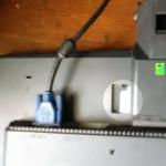
Among monitor malfunctions, there are quite often those that can be easily fixed with your own hands in a few minutes. For example, the already mentioned Acer AL1716 LCD monitor came to the repair table due to a broken contact of the socket outlet for connecting the power cord. As a result, the monitor turned off spontaneously.
After disassembling the LCD monitor, it was discovered that a powerful spark was formed at the site of the poor contact, traces of which were easy to detect on the printed circuit board of the power supply. A powerful spark was also formed because at the moment of contact the electrolytic capacitor in the rectifier filter is charged. The cause of the malfunction is solder degradation.

Solder degradation causing monitor failure
It is also worth noting that sometimes the cause of a malfunction can be a breakdown of the diodes of the rectifier diode bridge.