Not long ago I had the idea to practice making miniature devices. Without thinking twice, I went to the website of a regional seller of radio components and during the search process I came across a wonderful solution in the form of the TDA2822L microcircuit. Now about our sheep.
TDA2822L is a low-power, low-voltage integrated UMZCH, which has already been mentioned on this site (it seems like more than once). Its features are two channels, the ability to be powered from a voltage in the range of 1.8 - 12 V (unipolar), low losses, the ability to be switched on via a bridge circuit, and the presence of a solution in an SOP-8 package (not the smallest in nature, but still quite compact). And, by the way, “stupid” it has 1 W per channel (at a 4-ohm load). That is, even with large, powerful headphones, it’s enough for the eyes (more on that later). And it costs $0.37. A fairy tale, and nothing more!
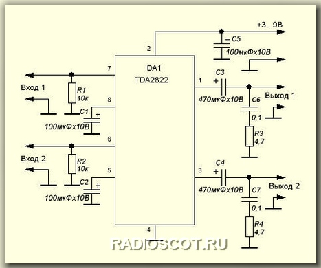
The wiring for it is minimal, and the UMZCH circuit, according to the datasheet, looks like this:
There is nothing fundamentally incomprehensible in this diagram, the details are typical, so let’s move straight to the interesting part, namely, the choice of parts.
Since we are assembling a miniature amplifier, it is clear that maximum quantity The parts must be in SMD version, in particular, I managed to make everything in SMD except C4 and C5 (well, our store doesn’t carry electrolytes for SMD installation). As for the power supply, it’s even more interesting - immediately from the moment the idea arose, I decided that I would power the circuit from a CR2032-type tablet, fortunately there is a wonderful small holder for them, and since almost all the elements are SMD, the space saving is good. But then, just in case, I decided to add two spots for the wires on the crown, just as a reserve.
Our total list of components:
Chip TDA2822L in SOP-8 package x1.
Resistor 10 kOhm 0805 x2
Resistor 4.7 kOhm 0805 x2
Capacitor 0.1 uF x2
Electrolytic capacitor 470 uF >10 V (I have 16 V) x2
The result is this cute “bobblehead”:

Disclaimer: I noticed that you can get rid of the R0 jumper, inherited from the previous revision of the board, after I soldered the board, so it’s too late and too lazy to fix it
As you can see, the dimensions are, ahem, small. To tell the truth, I didn’t even expect this, although the first version of the board was a little smaller and without a mask, but after making the signet it turned out that the electrolytes would have to be left hanging in the air. Combined with the poor quality of the board of the first version, I enlarged it a little and redesigned it, and everything went like clockwork (to be honest, almost like clockwork, one capacitor still “hangs”).
Note: on the board the chip itself is actually the opposite way around compared to the deeptrace design.
So, having a project in hand, we make a printed circuit board (if you like, I use FR + ammonium persulfate). A few photos of how this is done at home:


- 03.10.2014
The figure shows the power supply circuit for a GSM/GPRS module based on the TPS54260 chip, developed by Texas Instruments. The nominal input voltage in this circuit is 12 V, and the full operating range is 8 ... 40 V. The calculation methodology and test results are described in detail in the document “Creating GSM /GPRS Power Supply from TPS54260”. In the same document you can find a diagram for the rated voltage...
- 04.10.2014
There are quite a lot of power regulator circuits based on thyristors or triacs, where adjustment is carried out by changing the unlocking angle. Regulators with such a circuit create interference in the network, so they can only be used with bulky LC filters. In cases where it is not important that power is supplied to the load every half-cycle, but what matters is...
- 28.09.2014
The schematic diagram of such a player is shown in the figure. The amplifier is designed to operate on 4 speakers (2 front and 2 rear). The rear speakers are two-way, each consisting of one elliptical speaker of a fairly large diameter and one tweeter. The front channels are simpler - each consists of one full-range speaker. Rear channels have a rise in frequency response at frequencies above...
- 25.09.2014
The development of nuclear energy and the widespread use of sources of ionizing radiation in various fields of science and technology, as well as their possible appearance in everyday conditions, require familiarization with the properties and methods of recording alpha, beta and gamma radiation, as well as the acquisition of relevant knowledge and practical skills in protection from their influence. Assessing and conducting research...
- 21.09.2014
A time relay with a power of no more than 100 W with a delay time of about 10 minutes for turning off the lighting lamp can be assembled using schematic diagram shown in the figure. The device contains a rectifier bridge VD1-VD4, a thyristor VS1, a control transistor VT1 and a timing unit on capacitor C1, zener diode VD2 and transistor VT2. When closing the contacts of switch SA1 ...
I assembled a simple amplifier using a TDA2822M, and it worked right away
But due to an unsuccessful experiment, the micra burned out. Recently I came across a board with such a micro, and I decided to build such an amplifier again. So catch it
The microcircuit, of course, does not provide much, only 1W per channel, but for small speakers This is fine
Here is the circuit of a 2X1W amplifier on TDA2822M taken from the datasheet

Nothing complicated, minimal parts, I assembled the boards with grass in 20 minutes
Set of parts as usual
C1 = 1000mF (16V)
C2,4,6 = 100nF (104)
C3.7 = 470mF (16V)
C5.8 = 100mF (16V)
R1.3 = 10kOhm (brown - black - orange)
R2.4 = 4.7 Ohm (yellow - purple - gold)
Power supply 6-14V, 15V limit. Consumption 200mA
Assembled amplifier on a printed circuit board

Signet drawing from the track side

Signet for 2X1W amplifier on TDA2822M. Just like at home. This article has all the technology
Guard: If you have any problems with Motorola or Icom radios, then this company repairs professional radios at a low price. The company's engineers have qualitatively repaired more than 4,000 radio stations in the shortest possible time
Related Posts
I took the 3GDSH-1 speakers out of the TVs so that they wouldn’t lie idle and decided to make speakers, but since I have an external amplifier with a subwoofer, that means I’ll be assembling satellites.
Hello everyone, dear radio amateurs and audiophiles! Today I will tell you how to modify the high-frequency speaker 3GD-31 (-1300) also known as 5GDV-1. They were used in such acoustic systems as 10MAS-1 and 1M, 15MAS, 25AS-109…….
Hello dear readers. Yes, it’s been a while since I wrote a blog post, but with all responsibility I want to say that now I will try to keep up and write reviews and articles…….
Hello dear visitor. I know why you are reading this article. Yes, yes I know. No, what are you? I'm not a telepath, I just know why you ended up on this page. Surely......
And again, my friend Vyacheslav (SAXON_1996) wants to share his work on speakers. Word to Vyacheslav I somehow got one 10MAC speaker with a filter and a high-frequency speaker. I haven’t…… for a long time.
An old friend is better than two new ones!
Proverb
Thanks to its small number of wiring elements, the TDA2822M integrated circuit is one of the simple amplifiers, which can be assembled in a short time, connected to an MP3 player, laptop, radio - and immediately evaluate the result of your work.
This is how attractive the description looks:
"TDA2822M - stereo, two-channel low voltage amplifier for portable equipment, etc.
It can be bridged, used as a headphone or control amplifier, and much more.
Operating supply voltage: 1.8 V to 12 V, power up to 1 W per channel, distortion up to 0.2%. No radiator required.
Despite its super-miniature size, it produces honest bass. The ideal chip for beginners' inhumane experiences."
With my article, I tried to help fellow radio amateurs make experiments with this interesting chip more conscious and humane.
Let's look at the microcircuit housing
There are two microcircuits: one TDA2822, the other with the index “M” - TDA2822M.Integral chip TDA2822(Philips) designed to create simple power amplifiers audio frequency. The permissible range of supply voltages is 3…15 V; at Upit=6 V, Rн=4 Ohm, the output power is up to 0.65 W per channel, in the frequency band 30 Hz...18 kHz. Powerdip 16 chip package.
Chip TDA2822M it is made in a different Minidip 8 package and has a different pinout with a slightly lower maximum power dissipation (1 W versus 1.25 W for the TDA2822).
Please note that there are no other built-in output stage protection circuits for reasons of best use power supply, unfortunately, at the expense of reliability.
Pins 5 and 8 of the microcircuit are connected to the common wire via alternating current. In this case, the gain of the amplifier with a negative feedback will be:
Ku=20lg(1+R1/R2)= 20lg(1+R5/R4)=39 dB.
Block diagram The IC is shown in Fig. 2.

Rice. 2. Block diagram of TDA2822M
It was experimentally determined that the sum of the resistances of resistors R1+R2 and R5+R4 is equal to 51.575 kOhm. Knowing the gain, it is easy to calculate that R1=R5=51 kOhm, and R2=R4=0.575 kOhm.
To reduce the gain of an OOS microcircuit, an additional resistor is usually connected in series with R2 (R4). In this case, such a circuitry technique is “interfered” with open transistor switches on transistors Q12 (Q13).
But even if we assume that the keys do not affect the feedback gain, the maneuver to reduce the gain is insignificant - no more than 3 dB; otherwise, the stability of the amplifier covered by OOS is not guaranteed.
Therefore, you can experiment with changing the transmission coefficient of the amplifier, taking into account that the resistance of the additional resistor lies in the range of 100...240 Ohms.
Rice. 3. Schematic diagram of an experimental stereo amplifier
The amplifier has the following characteristics:
Supply voltage Up=1.8…12 V
Output voltage Uout=2…4 V
Current consumption in quiescent mode Io=6…12 mA
Output power Pout=0.45…1.7 W
Gain Ku=36…41 (39) dB
Input resistance Rin=9.0 kOhm
Crosstalk attenuation between channels is 50 dB.
From a practical point of view, for reliable operation of the amplifier, it is advisable to set the supply voltage to no more than 9 V; in this case, for a load Rн=8 Ohm the output power will be 2x1.0 W, for Rн=16 Ohm - 2x0.6 W and for Rн=32 Ohm - 2x0.3 W. With load resistance Rн=4 Ohm, the optimal supply voltage will be up to 6 V (Pout=2x0.65 W).
The gain of the microcircuit of 39 dB, even taking into account a small downward adjustment by resistors R5, R6, turns out to be excessive for modern signal sources with a voltage of 250...750 mV. For example, for Up=9 V, Rн=8 Ohm, the sensitivity from the input is about 30 mV.
In Fig. 4, and the amplifier connection circuit is shown, allowing you to connect personal computer, MP3 player or radio with a signal level of about 350 mV. For devices with an output signal of 250 mV, the resistance of resistors R1, R2 must be reduced to 33 kOhm; at an output signal level of 0.5 V, resistors R1=R2=68 kOhm, 0.75 V – 110 kOhm should be installed.
Double resistor R3 sets the required volume level. Capacitors C1, C2 are transitional.
Rice. 4. UMZCH connection diagram: a) - k acoustic systems, b) – to headphones (headphones)
In Fig. 4, b shows the connection to the amplifier of the headphone jack. Resistors R4, R5 eliminate clicks when connecting stereo phones, resistors R6, R7 limit the volume level.
During the experiments, I tried to power the UMZCH both from a stabilized power supply (on integrated circuit and transistor BD912), Fig. 5, and from a battery with a capacity of 7.2 Ah for a voltage of 12 V with a power supply for fixed voltages, Fig. 6.
The supply voltage is supplied by as short a pair of wires as possible, twisted together.
Right assembled device does not need adjustment.
Fragment excluded. Our magazine exists on donations from readers. The full version of this article is available only
Rice. 5. Schematic diagram of a stabilized power supply
Fragment excluded. Our magazine exists on donations from readers. The full version of this article is available only
Rice. 6. Battery– laboratory power supply
A subjective assessment of the noise level showed that when the volume control is set to the maximum level, the noise is barely noticeable.
Subjective assessment of sound reproduction quality was made without comparison with the standard. The result is a good sound, listening to soundtracks does not cause irritation.
I checked out the microcircuit forums on the Internet, where I came across a lot of messages about searching for unknown sources of noise, self-excitation and other troubles.
As a result, I developed a printed circuit board, distinctive feature which is the “star” grounding of the elements. A photo view of the printed circuit board from the Sprint-Layout program is shown in Fig. 7.
Fragment excluded. Our magazine exists on donations from readers. The full version of this article is available only
Rice. 7. Placement of parts on the experimental printed circuit board
During experiments on this signet, it was not possible to encounter any of the artifacts described on the forums.
Details of the stereo UMZCH on the TDA2822M chip
The printed circuit board is designed for installation of the most common parts: MLT, S2-33, S1-4 or imported resistors with a power of 0.125 or 0.25 W, film capacitors K73-17, K73-24 or imported MKT, imported oxide capacitors.
I used inexpensive but reliable electrolytic capacitors with low impedance, long service life (5000 hours) and the ability to operate at temperatures up to +105°C from Hitano ESX, EHR and EXR series. It should be remembered that the larger the outer diameter of the capacitor in the series, the longer its service life.
The DA1 chip is installed in an eight-pin socket. The TDA2822M chip can be replaced with KA2209B (Samsung) or K174UN34 (Angstrem OJSC, Zelenograd). CHIP capacitor C8 (SMD) is located on the side of the printed tracks.
R5, R6 - Res.-0.25-160 Ohm (Brown, blue, brown, golden) - 2 pcs.,
C3 - C5 - Cond. 1000/16V 1021+105°C - 3 pcs.,
C6, C7 - Cond. 0.1/63V K73-17 - 2 pcs.,
C8 - Cond.0805 0.1µF X7R smd – 1 pc.
Many radio amateurs, not without reason, believe that it is best to include microcircuits in accordance with the Datasheet and use printed circuit boards offered by the developers.
Below are diagrams and printed circuit boards made on the basis of the documentation with the only modification - to increase the stability of the amplifier, a film capacitor is connected in parallel with the oxide capacitor along the power circuit (Fig. 8, 9).
Fragment excluded. Our magazine exists on donations from readers. The full version of this article is available only
Rice. 8. Typical scheme turning on the microcircuit in stereo mode
Fragment excluded. Our magazine exists on donations from readers. The full version of this article is available only
Rice. 9. Placement of elements of a typical stereo UMZCH
Details of a typical stereo UMZCH
When installing elements on a printed circuit board, I advise you to use simple technological techniques described in the Datagorsk article.
DA1 - TDA2822M ST Housing: DIP8-300 - 1 pc.,
SCS-8 Narrow dip socket - 1 pc.,
R1, R2 - Res.-0.25-10k (Brown, black, orange, golden) - 2 pcs.,
R3, R4 - Res. -0.25-4.7 Ohm (Yellow, purple, golden, golden) - 2 pcs.,
C1, C2 - Cond. 100/16V 0611 +105°C - 2 pcs.,
C3 - Cond. 10/16V 0511 +105°C (Capacity can be increased to 470 µF) - 1 pc.,
C4, C5 - Cond.470/16V 1013+105°C - 2 pcs.,
C6 – C8 - Cond. 0.1/63V K73-17 - 3 pcs.
Rice. 10. Schematic diagram of an experimental bridge amplifier
Unlike the stereo amplifier circuit (Fig. 3), which assumes that coupling capacitors are present at the output of the previous device, a coupling capacitor is included at the input of the bridge amplifier, which determines the lower frequency reproduced by the amplifier.
Depending on the specific application, the capacitance of capacitor C1 can be from 0.1 μF (fn = 180 Hz) to 0.68 μF (fn = 25 Hz) or more. With capacitance C1 indicated on the circuit diagram, the lower frequency of the reproduced frequencies is 80 Hz.
Internal resistors connected to the inverting inputs of the amplifier through an isolation capacitor C2 are connected to each other, which provides output signals of equal magnitude but opposite in phase.
Capacitor C3 performs correction frequency response amplifier at high frequencies.
Since the potentials of the amplifier outputs are DC are equal, it became possible to directly connect the load, without isolating capacitors.
The purpose of the remaining elements was described earlier.
For the stereo version, you will need two bridge amplifiers on the TDA2822M chip. The connection diagram is easy to obtain using Fig. 4.
Reliable operation of the amplifier in bridge mode is ensured by selecting the appropriate supply voltage depending on the load resistance (see table).

All parts of the bridge amplifier are placed on a printed circuit board measuring 32 x 38 mm, made of one-sided foil fiberglass 2 mm thick. Drawing possible option The board is shown in Fig. 11.

Rice. 11. Placement of elements on the bridge amplifier board
DA1 - TDA2822M ST Housing: DIP8-300 - 1 pc.,
SCS-8 Narrow dip socket - 1 pc.,
R1 - Res.-0.25-10k (Brown, black, orange, gold) - 1 pc.,
R2, R3 - Res. -0.25-4.7 Ohm (Yellow, purple, golden, golden) - 2 pcs.,
C1 - Cond. 0.22/63V K73-17 - 1 pc.,
C2 - Cond. 10/16V 0511 +105°C - 1 pc.,
C3 - Cond.0.01/630V K73-17 - 1 pc.,
C4 – C6 - Cond.0.1/63V K73-17 - 3 pcs.,
C7 - Cond. 1000/16V 1021+105°C - 1 pc.
The schematic diagram of a typical bridge UMZCH and the placement of elements on the printed circuit board are shown respectively in Fig. 12 and 13.
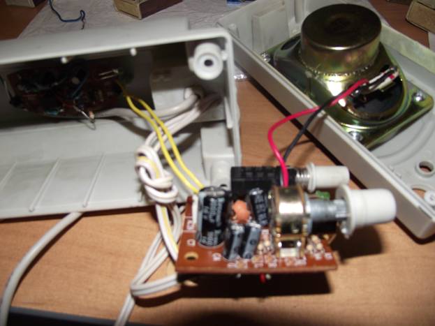
The conversation will be in this article about Chinese-made speakers for a computer based on the TDA2822 chip. I got this column - though only one. The amplifier turned out to be alive, but the plugs, power supply and second speaker were not included. Here is a photo of this computer speaker:The photo shows a creative mess and the speaker is already in working order. But as you understand, before that she was not in working condition. So, the task:
1. Just revive the speakers
2. Make them work from Computer USB or laptop (since I didn't have a power supply to power these speakers)
3. Mobility. It’s easier to carry one speaker with you for computer repairs)
4. Possibility of powering these speakers from batteries.
Let's start resuscitating the speakers, for this we will need: A standard soldering kit (tin, rosin, soldering iron), as well as several wires, a 180 ohm resistor, USB extension cable- must have a male-female plug, such as for example used to extend the mouse cable. And we will also need a zaryannik for the cell from the cigarette lighter. The charger is needed for nokia phones, assembled on the mc34063 chip. I think you can choose a soldering iron yourself, but we need a USB cord like this:

The longer the cord, the more convenient it is to work with it. It can be purchased at any computer store. In our case, this cord will be used to power the speakers via USB. The wires in the cord are colored. We need a BLACK minus and a RED plus. Any resistor can be used - I took a 150 ohm smd, but I couldn’t find one for 180 ohms. Now about the main thing! About the charger from which we will sculpt the converter.
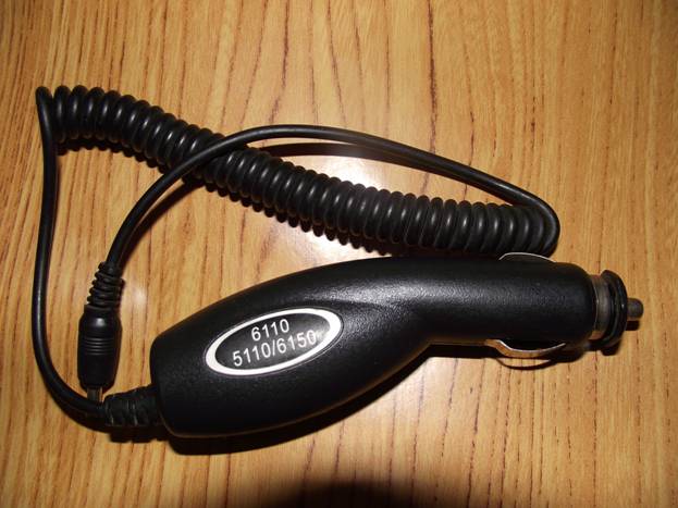
Quite a few chargers have been tested, but this model turned out to be the most reliable and convenient for alteration.
1. You don’t have to buy any additional parts; everything is already on the board (except for one resistor).
2. Eat right away PCB the alteration of which is minimal
3. The converter board fits perfectly in the mounting column instead of the transformer.
4. This type The charger has NEVER FAILED, unlike other models - everything works right away.
5. All part values are immediately indicated on the board - this is very convenient.
6. These chargers are always assembled on the mc34063 chip, which is the most important factor for us.
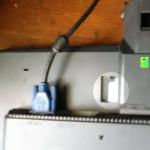
Inside charger looks like this:

The photo came out poorly, but in principle everything is clear. This converter is assembled as a step-down converter, but we need to make a boost converter out of it (fortunately, this can be done without much difficulty). To make it easier for you to navigate when remaking, here are two diagrams. A variant of a step-down converter - the circuit simply does not have an indicator LED and a polarity reversal diode is present in the charger itself. If you assemble the circuit yourself, I don’t see any point in complicating the circuit and adding these elements. But in the finished circuit I simply didn’t solder them, and they don’t bother me.

Boost version of the supply voltage converter:
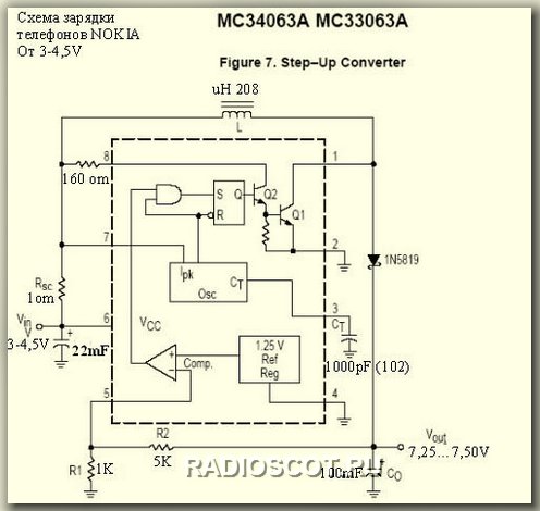
As you can see, the alteration is minimal. You just need to cut a few tracks on the board and re-solder the diode and inductor in places, and you can leave the inductor as original - everything will work perfectly. Oh yes, I almost forgot, you will have to add one 180 ohm resistor to the circuit and that’s it. If you were satisfied with this before output voltage your converter, then you won’t have to touch anything and after the conversion it will remain the same. If you need a different voltage, then simply select R2 according to the diagram - the higher the output voltage, the more difficult it is to select the resistance R2, and on the contrary, if you need less voltage at the output, then select a smaller resistor resistance. In principle, to calculate the wiring of a given microcircuit, there are many calculators on the network, so there will be no problems with this.
In my case, a voltage of at least 10-11V was needed. This was done by selecting resistor R2. After modification, this converter can be powered from 3 to 6V, which, if necessary, will allow this amplifier to be powered even from a battery mobile phone. In this case, the output of the converter will always have a stable voltage. According to this scheme, several chargers were assembled for cell phones from batteries. The minimum power supply for the microcircuit is 3V, the maximum is 40V. You can look at this in more detail in the datasheet for the mc34063 chip. The finished device looks like this:

Everything could easily fit back into the cigarette lighter housing.

The view is already inside the column. Worth instead standard block nutrition.
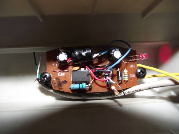
Here is the amplifier itself on the TDA2822 chip; on its board there is a volume control and a power switch:
To complete the picture, I will give a diagram from the datasheet for the TDA2822 stereo amplifier chip:
Maximum permissible voltage power supply for the TDA2822 chip is 10V. Although I tried from 14V, I don’t advise you to repeat it, you never know. Well, that's all, now your speakers can be powered from USB, from a charger for a player or cell phone, or from batteries. And if you put batteries inside, it will be completely universal. See the finished version of the column at the beginning of the article. Material sent by A. Kulibin
Discuss the article SPEAKERS WITH AMPLIFIER ON TDA2822