While doing home repairs, I was faced with the need to draw a single-line power supply diagram. Everything could have been done by hand, but I decided to do it on a computer. This review is dedicated to free programs for preparing single-line electrical circuits.
What is a single line power supply scheme?
A one-line diagram is a technical document that GENERALLY gives the person working with it an idea of:
Connection points of the object;
- The main loads and their indicators (power of machines, their nominal value, marking, etc.);
- Supply cable (again, all its characteristics: type, permitted current, etc.);
- Rated current of the input device at the connection point and protective switching devices (similarly);
- The main consumers of electricity at the facility (similarly).
In fact, without a single-line power supply circuit, it is UNREAL to carry out electrical work. Since the main thing in the document is information.
What is a circuit diagram
A circuit diagram is a drawing showing the complete electrical and magnetic and electromagnetic connections of the elements of an object, as well as the parameters of the components that make up the object depicted in the drawing.
Why is the circuit called single-line?
A single-line diagram is the same electrical circuit diagram, but made in a simplified form: all lines of single-phase and three-phase networks are depicted as one line.
Example of a single-line electrical circuit
How to draw a single-line electrical circuit
There are a lot of programs for drawing on a computer (yes, yes, electrical circuits are not drawn, but drawn!) But all of them are usually difficult to master if you are not doing it professionally. However, I have found a few that are easy for the average person to use.
Program 1-2-3 scheme
The HAGER software 1-2-3-diagram, Semiolog and hLsys Lume are distributed free of charge. You can and should download from the official website http://www.hagersystems.ru/software/. And do not look for it in file cleaning and garbage collection. Program in Russian. 
The program "1-2-3 scheme" allows you to select the body of the electrical panel in accordance with the requirements for the degree of protection, equip it with protective and switching modular devices, set the hierarchy for connecting modular devices and automatically generate a single-line diagram of the shield.
The program allows you to correctly select the series of the case and its size, based on the number of modular devices, arbitrarily mark the modular devices. The element base of the program 1-2-3-scheme contains the actual article numbers of equipment supplied to the Russian market and certified according to Russian and European standards. Using the 1-2-3-scheme, you can correctly draw up a specification, create a single-line electrical panel diagram and draw its appearance. 
It is clear that it is not at all necessary to use the element base of the HAGER manufacturer. The main thing is the result, that is, a single-line diagram, the correct size of the shield body (when there is enough space for all the machines) and, as a bonus, label printing, which can then be pasted on the shield above the machines.
Using the program 1-2-3 scheme, you can easily and with minimal time to create an electrical circuit board for housing construction. In order to make better use of the program's capabilities and make better use of time, hager has developed an interface between this new program and the semiolog labeling program.
For work, you can use only the mouse, develop and print a diagram of an electrical panel and labels with designations for the elements of the circuit for the shield. 
An example of an assembled board with consumer group markings made in the Semiolog program.
XL Pro² Program by Legrand

The second program, also from the manufacturer, is Legrand's XL Pro², which simplifies the design of low-voltage switchgear (LVD).
The program allows the designers of switchboards to design switchboards and switchboards of the XL³ series in two ways:
- using a single line diagram.
The program will automatically determine the type of the complete device, calculate its cost, and place the equipment. XL Pro² automatically makes all changes, which makes it as easy as possible to design and calculate various types of cabinets.
XL Pro is free and available for download by registered Extranet users.
PROGRAM XL PRO³
The XL Pro³ software simplifies the design of low voltage switchgear (LVD).
The program allows designers of low-voltage switchgear to design distribution cabinets and switchboards manufactured by Legrand for currents up to 6300 A using two methods:
- select Legrand equipment from the proposed list, necessary for cabinet assembly;
- using a single line diagram.
The program will automatically determine the type of the complete device, calculate its cost, and place the equipment. XL Pro³ automatically makes all changes, which makes it as easy as possible to design and calculate various types of cabinets.
You can download the program on the official website - http://www.legrand.ru/ru/scripts/ru/publigen/content/templates/previewMultiPhoto.asp?P=1715&L=EN
Rapsodie - Switchboard layout
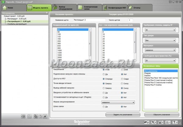
This is the third program in the overview for the layout of switchboards, but now from schneider-electric.
- Rapsodie is designed for the assembly of Prisma Plus, Pragma and Kaedra series low-voltage cabinets.
- Working in Rapsodie greatly speeds up the cabinet layout process.
- As a result of working with the program, the user can get: the appearance of the cabinet and a complete assembly specification, as well as a detailed calculation of the project cost.
- The program database contains Schneider Electric devices, the user can automatically select additional accessories for them. It is also possible to create a personal directory from devices that are not in the program database.
- Rapsodie also allows you to choose to display the single-line diagram topology for the correct selection of switchgear and mounting accessories.
- The program has a mode of automatic selection of a cell of the desired configuration, taking into account previously specified criteria.
- The program has an attractive and intuitive Russian-language interface, documentation is issued in the form of files of common formats (*.txt, *.xls, *.pdf, *.dxf).
Advantages
Rapsodie is an intelligent switchboard layout tool.
- Comfort and transparency when working in the program
- Automatic device compatibility check
- Quick access to design results
- Print or export complete supporting documentation
As a result of working with the program, the User can get: the appearance of the cabinet (doors, front panels, devices, mounting plates, composite devices) and a complete assembly specification, a detailed calculation of the project cost (including taking into account assembly and commissioning works, as well as taking into account discounts).
The program has an attractive and intuitive Russian-language interface, documentation is created in the form of documents in common formats (*.txt, *.xls, *.pdf, *.dxf). Working with Rapsodie significantly speeds up the cabinet layout process and minimizes the possibility of errors.
The program is free, but just like in the case of Legrand, it is not freely available. The program is distributed among the clients and partners of ZAO Schneider Electric free of charge. For maximum user convenience in mastering Rapsodie, a training course is held at the Schneider Electric Learning Center.
The application form for the program can be found on the website, in the Rapsodie product section. The completed application should be sent to the Customer Support Center at [email protected]
Drawing on paper is far from fun for everyone - it takes a long time, it’s not always beautiful, it’s hard to immediately correctly calculate the dimensions, and it’s inconvenient to make adjustments. All these problems are easily solved by the program for drawing diagrams. Most modern software products contain a library with a set of basic elements. From them, as from the constructor, the required configuration is assembled. Edits and corrections are made quickly, you can save different versions.
There are quite a few electrical drawing programs that you can use for free. Some of these are demo versions with limited functionality, some of them are full-fledged products. For designing a wiring diagram in an apartment or house, these functions are enough, but for professional use, a product with wider functionality may be required. For these purposes, paid options are more suitable.
Like any software product, a diagram drawing program is rated for ease of use. The interface should be simple, convenient, functional. Then even a person without special computer skills can easily figure it out. But, nevertheless, the main factor is the sufficiency of functions for creating circuits of varying complexity. After all, even an inconvenient interface can be adapted, but the absence of some parts is more difficult to make up for.
A simple program for drawing diagrams VISIO
Many of us are familiar with Microsoft office products and Visio is one of the products. This graphics editor has a familiar interface for Microsoft products. Extensive libraries contain all the necessary element base, you can create circuit, wiring diagrams. Working in VISIO is easy: in the library (window on the left) we find the desired section, look for the required element in it, drag it to the working field, put it in place. The dimensions of the elements are standardized, they fit one with the other without problems.

Vision program for drawing diagrams - a clear interface
What's nice is that you can create diagrams to scale, which will make it easier to calculate the required length of wires and cables. What’s more good is that it doesn’t take much space on the computer’s hard drive, even not very powerful machines will “pull” this program for drawing diagrams. Also pleased with the presence of a large number of video tutorials. So there won't be any problems with learning.
Clear ProfiCAD
If you need a simple program for the design of electrical wiring - pay attention to ProfiCAD. This product does not require downloading libraries like most others. The database contains about 700 built-in elements, which are enough to develop a power supply scheme for an apartment or a private house. The available elements are also sufficient to draw up not too complex circuit diagrams. If an element is missing, it can be added.
The main drawback of the program for drawing ProfiCAD diagrams is the lack of a Russified version. But, even if you are not strong in English, it is worth a try - everything is very simple. In a couple of hours you will master everything.

The principle of operation is simple: in the field on the left we find the desired element, drag it to the right place in the diagram, and rotate it to the desired position. Let's move on to the next element. After completing the work, you can get a specification indicating the number of wires and a list of elements, save the results in one of four formats.
Compass Electric
A program with more serious functionality is called Compass Electric. It is part of the Compass 3D software. In it, you can not only draw a circuit diagram, but also block diagrams and much more. At the output, you can get specifications, purchasing lists, connection tables.
To get started, you need to download and install not only the program, but also a library with an element base. The program, explanations, help - everything is Russified. So there will be no problems with the language.
When working, select the desired section of the library, graphic images appear in a pop-up window. In it, select the necessary elements, drag them to the working field, setting them in the right place. As the scheme is formed, the data about the elements get into the specification, where the name, type and denomination of all elements are fixed.
The numbering of elements can be put down automatically, or maybe manually. The method is selected in the settings menu. You can change it during work.
QElectroTech
Another program for drawing circuits is QElectroTech. The interface resembles Microsoft products and is easy to work with. There is no need to download a library for this program, the element base is "built-in". If something is not there, you can add your own elements.
The finished scheme can be saved in the get format (for further work with it in the program) or as an image (jpg, png, svg, bmp formats). After saving, you can change the dimensions of the drawing, add a grid, a frame.

QElectroTech - free editor for creating electrical circuits
This program has some drawbacks. The first is that inscriptions can be made in only one font, that is, if you need a drawing in accordance with GOST, you will have to somehow figure out how to change the font. The second is that the sizes of frames and stamps are set in pixels, which is very inconvenient. In general, if you need a program for drawing diagrams for home use, this is a great option. If compliance with the requirements of GOST is required, look for another.
123D Circuits Electronic Circuit Simulator
If you do not know how to draw a diagram on a computer, take a closer look at this product. 123D Circuits is an online service that allows you to create a not very complex circuit with the ability to create printed circuit boards. There is also a built-in simulator that simulates the work of the finished circuit. The function of ordering a batch of ready-made boards is available (for a fee).

Before you start, you need to register, create your profile. After that, you can start work. Multiple users can work on the same project using shared libraries. In the free version of the program, you can create an unlimited number of schemes, but they will be publicly available. In the amateur tariff ($12), five circuits can be personal, and there is also a 5% discount on the production of circuit boards. The Professional plan ($25) gives you an unlimited number of personal designs and the same discount on ordering boards.
The circuit can be drawn from the available components (there are not very many of them, but it is possible to add your own) or imported from the Eagle program. Unlike other programs, the 123D Circuits library does not contain schematic symbols of elements, but their mini copies. Interface with two side fields. On the right, the section of the library with the element base is displayed, on the left - part of the settings and the list of used elements. After the work is completed, the program itself generates a circuit diagram, and also suggests the location of elements on the board (can be edited).
Everything seems to be fine, but 123D Circuits has serious drawbacks. First, the results of simulated work are often very different from real readings. The second - the functionality is small, it will not work to make a really complex circuit. Conclusion: Basically, this program is suitable for students and beginner radio amateurs.
Paid programs for drawing electrical circuits
There are many paid graphic editors for creating diagrams, but not all of them are needed for "home" use or for work, but not directly related to design. Paying a lot of money for unnecessary features is not the smartest decision. In this section, we will collect those products that have received a lot of good reviews.
DipTrace - for PCB design
For experienced radio amateurs or those whose work is related to the design of radio products, the DipTrace program will be useful. It was developed in Russia, therefore it is completely in Russian.
It has a very useful function - it can develop a printed circuit board according to a ready-made scheme, and it can be seen not only in two-dimensional, but also in a three-dimensional image with the location of all elements. It is possible to edit the position of elements on the board, develop and correct the device case. That is, it can be used both for designing wiring in an apartment or house, and for developing some devices.

In addition to the program for drawing diagrams, you will also need to download a library with an element base. The peculiarity is that this can be done using a special application - Schematic DT.
The interface of the program for drawing circuits and creating printed circuit boards DipTrace is convenient. The process of creating a scheme is standard - we drag the necessary elements from the library onto the field, expand them in the required direction and set them in place. The element currently being worked on is highlighted, which makes the work more comfortable.
As the scheme is created, the program automatically checks the correctness and admissibility of connections, the coincidence of sizes, compliance with gaps and distances. That is, all edits and adjustments are made immediately, at the creation stage. The created circuit can be run on the built-in simulator, but it is not the most difficult, so it is possible to test the product on any external simulators. It is possible to import a scheme to work in other applications or accept (export) an already created one for its further development. So the DipTrase circuit drawing program is a really good choice.
If you need a printed circuit board, we find the corresponding function in the menu, if not, the circuit can be saved (it can be corrected) and / or printed. The DipTrace diagramming program is paid (there are different tariffs), but there is a free 30-day version.
SPlan
Perhaps the most popular program for drawing diagrams is SPlan. It has a well thought out interface, extensive, well structured libraries. It is possible to add your own elements if they are not in the library. As a result, it is easy to work, the program is mastered in a few hours (if you have experience with similar software).
The disadvantage is that there is no official Russified version, but you can find it partially translated by craftsmen (the help is still in English). There are also portable versions (SPlan Portable) that do not require installation.

One of the most "light" versions - SPlan Portable
After downloading and installing the program, you need to configure it. This takes a few minutes, the settings are saved on subsequent launches. The creation of schemes is standard - we find the desired element in the window to the left of the working field, drag it into place. The numbering of elements can be put down in automatic or manual mode (selected in the settings). What's nice is that you can easily change the scale - by scrolling the mouse wheel.
There is a paid (40 euros) and a free version. The free one disables saving (bad) and printing (you can bypass it by creating screenshots). In general, according to numerous reviews, it is a worthwhile product that is easy to work with.
The times of using drawing boards have long passed, they have been replaced by graphic editors, these are special programs for drawing electrical circuits. Among them there are both paid applications and free ones (we will consider the types of licenses below). We are sure that the short review we have created will help you choose the most optimal software for your task from a variety of software products. Let's start with the free versions.
Free
Before proceeding to the description of the programs, we will briefly talk about free licenses, the most common of them are the following:
- Freeware- the application is not limited in functionality and can be used for personal purposes without a commercial component.
- open source- a product with an "open source", in which it is allowed to make changes by adjusting the software to suit your own tasks. There may be restrictions on commercial use and paid distribution of the modifications made.
- GNU GPL- a license that practically does not impose any restrictions on the user.
- public domain- almost identical to the previous version, the copyright law does not apply to this type of license.
- Ad-supported- the application is fully functional, contains advertising of other products of the developer or other companies.
- donationware– the product is distributed free of charge, but the developer offers to make donations on a voluntary basis for the further development of the project.
Once you have an idea about free licenses, you can move on to software distributed under such terms.
Microsoft Visio
This is an easy-to-manage, but at the same time very convenient vector graphics editor with a rich functional set. Despite the fact that the main socialization of the program is the visualization of information from MS Office applications, it can be used to view and print radio diagrams.
MS releases three paid versions that differ in functionality and a free one (Viewer), which integrates into the IE browser and allows you to use it to view files created in the editor. Unfortunately, for editing and creating new schemes, you will need to purchase a full-featured product. Note that even in paid versions, among the basic templates there is no set for the full creation of radio circuits, but it is easy to find and install.
Disadvantages of the free version:
- The functions of editing and creating diagrams are not available, which significantly reduces interest in this product.
- The program works only with the IE browser, which also creates a lot of inconvenience.
Compass-Electric
This software is an application to the CAD system of the Russian developer ASCON. It requires the installation of the KOMPAS-3D environment for its operation. Since this is a domestic product, it fully supports the GOSTs adopted by Russia, and, accordingly, there are no problems with localization.

The application is intended for designing any types of electrical equipment and creating sets of design documentation for them.
This is paid software, but the developer gives 60 days to get acquainted with the system, during this time there are no restrictions on functionality. On the official website and on the network you can find a lot of video materials that allow you to get acquainted with the software product in detail.
In the reviews, many users note that the system has a lot of flaws that the developer is in no hurry to fix.
Eagle
This software is a comprehensive environment in which you can create both a circuit diagram and a printed circuit board layout for it. That is, place all the necessary elements on the board and trace. At the same time, it can be performed both in automatic and manual mode or by a combination of these two methods.

There are no models of domestic radio components in the basic set of elements, but their templates can be downloaded online. The language of the application is English, but localizers that allow you to install the Russian language.
The application is paid, but the possibility of using it for free with the following functional limitations:
- The size of the circuit board cannot exceed 10.0 x 8.0 cm.
- When routing, only two layers can be manipulated.
- The editor is allowed to work with only one sheet.
dip trace
This is not a separate application, but a whole software package that includes:
- Multifunctional editor for the development of circuit diagrams.
- Application for creating circuit boards.
- 3D module that allows you to design housings for devices created in the system.
- A program for creating and editing components.

The free version of the software package, for non-commercial use, has some minor limitations:
- Circuit board no more than 4 layers.
- No more than one thousand outputs from components.
The program does not provide for Russian localization, but it, as well as a description of all the functions of the software product, can be found on the net. There are also no problems with the component base, initially there are about 100 thousand of them. On thematic forums, you can find component databases created by users, including those for Russian GOSTs.
1-2-3 scheme
This is a completely free application that allows you to complete Hager electrical panels with the equipment of the same name.

Functionality of the program:
- Choice of housing for the electrical panel that meets the standards for the degree of protection. The selection is made from the Hager range.
- Completion with protective and switching modular equipment of the same manufacturer. Note that the element base contains only models certified in Russia.
- Formation of design documentation (single-line diagram, specifications that meet the ESKD standards, rendering of the appearance).
- Creation of markers for switching devices of the electrical panel.
The program is completely localized for Russian, its only drawback is that only the electrical equipment of the developer company is present in the element base.
Autocad Electrical
An application based on the well-known CAD Autocad, created for the design of electrical circuits and the creation of technical documentation for them in accordance with the ESKD standards.

Initially, the database includes over two thousand components, while their conditional graphic designations meet the current Russian and European standards.
This application is paid, but it is possible to get acquainted with the full functionality of the basic working version within 30 days.
Elf
This software is positioned as an automated workstation (AWP) for electrical designers. The application allows you to quickly and correctly develop almost any drawing for electrical projects with reference to the floor plan.
Application functionality includes:
- Arrangement of UGO when designing electrical networks laid openly, in pipes or special structures.
- Automatic (from the plan) or rune calculation of the power circuit.
- Preparation of specifications in accordance with current regulations.
- The possibility of expanding the base of elements (UGO).

The free demo version does not include the ability to create and edit projects, they can only be viewed or printed.
Kicad
This is a completely free software package with open source (Open Source). This software is positioned as an end-to-end design system. That is, it is possible to develop a schematic diagram, create a circuit board according to it and prepare the documentation necessary for production.

Characteristic features of the system:
- It is allowed to use external tracers for PCB layout.
- The program has a built-in PCB calculator, the placement of elements on it can be done automatically or manually.
- Upon completion of the trace, the system generates several technological files (for example, for a photoplotter, a drilling machine, etc.). If desired, you can add a company logo to the printed circuit board.
- The system can create a layered printout in several popular formats, as well as generate a list of components used in the development to form an order.
- It is possible to export drawings and other documents to pdf and dxf formats.
Note that many users note the ill-conceived interface of the system, as well as the fact that in order to master the software, you need to study the documentation for the program well.
TinyCAD
Another free and open source application that allows you to create circuit diagrams and has the functions of a simple vector graphics editor. The base set contains forty different component libraries.
 TinyCAD - simple editor for schematic diagrams
 The program does not provide PCB routing, but it is possible to export the netlist to a third-party application. Export is made with support for common extensions.
The application supports only English, but thanks to the intuitive menu, there will be no problems with mastering.
Fritzing
Free project development environment based on Arduino. It is possible to create printed circuit boards (wiring must be done manually, since the autorouting function is frankly weak).

It should be noted that the application is "sharpened" to quickly create sketches that allow you to explain the principle of operation of the designed device. For serious work, the application has too small a base of elements and a highly simplified schema.
123D Circuits
This is a web application for developing Arduino projects, with the ability to program the device, simulate and analyze its work. In a typical set of elements, there are only basic radio components and Arduino modules. If necessary, the user can create new components and add them to the database. It is noteworthy that the developed printed circuit board can be ordered directly from the online service.

In the free version of the service, you cannot create your own projects, but you can view other people's developments that are in the public domain. For full access to all features, you need to subscribe ($12 or $24 per month).
Note that due to the poor functionality, the virtual development environment is of interest only to beginners. Many of those who used the service drew attention to the fact that the simulation results diverge from the real figures.
XCircuit
Free multi-platform application (GNU GPL license) for quick circuit diagram creation. The functional set is minimal.

The language of the application is English, the program does not accept Russian characters. You should also pay attention to the atypical menu, which you need to get used to. In addition, contextual hints are displayed on the status bar. The basic set of elements includes the UGO of only the main radio components (the user can create his own elements and add them).
CADSTAR Express
This is a demo version of the CAD of the same name. Functional limitations affected only the number of elements used in the development scheme (up to 50 pieces) and the number of contacts (no more than 300), which is quite enough for small amateur radio projects.

The program consists of a central module, which includes several applications that allow you to develop a circuit, create a board for it and prepare a package of technical documentation.
The basic set includes more than 20,000 components, additional libraries can be downloaded from the developer's website.
A significant drawback of the system is the lack of support for the Russian language, respectively, all technical documentation is also presented online in English.
QElectroTech
Simple convenient and free (FreeWare) application for the development of electrical and electronic circuit drawings. The program is a regular editor, no special functions are implemented in it.

The language of the application is English, but there is a Russian localization for it.
Paid Apps
Unlike software distributed under free licenses, commercial programs, as a rule, have much more functionality and are supported by developers. As an example, we present several such applications.
sPlan
A simple editor program for drawing electrical circuits. The application comes with several component libraries that the user can expand as needed. You can work with several projects at the same time by opening them in separate tabs.

The drawings made by the program are stored as vector graphics files of their own format with the "spl" extension. Converting to standard raster image formats is allowed. It is possible to print large diagrams on a regular A4 printer.
Officially, the application is not released in Russian localization, but there are programs that allow you to Russify the menu and contextual tips.
In addition to the paid version, there are two free implementations of Demo and Viewer. In the first, there is no way to save and print the drawn diagram. The second provides only the function of viewing and printing files of the "spl" format.
Eplan Electric
Multi-module scalable CAD for the development of electrical projects of varying complexity and automation of the process of preparing design documentation. This software package is now positioned as a corporate solution, so it will not be of interest to ordinary users, especially if we take into account the cost of the software.

Target 3001
A powerful CAD system that allows you to develop electrical circuits, trace printed circuit boards, and simulate the operation of electronic devices. The online library of components has more than 36 thousand different elements. This CAD is widely used in Europe for PCB routing.

English is set by default, it is possible to set the menu in German or French, there is no official Russian localization. Accordingly, all documentation is provided only in English, French or German.
The cost of the simplest basic version is about 70 euros. For this money, tracing of two layers for 400 pins will be available. The cost of the unlimited version is around 3.6 thousand euros.
Microcap
An application for modeling digital, analog and mixed circuits, as well as analyzing their work. The user can create an electrical circuit in the editor and set parameters for analysis. After that, with one click of the mouse, the system will automatically make the necessary calculations and display the results for study.

The program allows you to set the dependence of the parameters (values) of the elements on the temperature regime, illumination, frequency characteristics, etc. If there are animated elements in the circuit, for example, LED indicators, then their state will be correctly displayed, depending on the incoming signals. It is possible to “connect” virtual measuring instruments to the circuit during simulation, as well as monitor the status of various device nodes.
The cost of the full-featured version is about $4.5 thousand. There is no official Russian localization of the application.
TurboCAD
This CAD platform includes many tools for designing various electrical devices. A set of special functions allows you to solve engineering and design problems of any complexity.

Distinctive features - fine-tuning the interface for the user. A lot of reference literature, including in Russian. Despite the lack of official support for the Russian language, there are localizers for the platform.
For ordinary users, the purchase of a paid version of the program in order to develop electrical circuits for amateur devices will be unprofitable.
Designer Schematic
An application for creating electrical circuits using radio elements manufactured by Digi-Key. The main feature of this system is that in the editor for constructing diagrams, mechanical design can be used.

Component databases can be checked for compliance at any time and, if necessary, updated directly from the manufacturer's website.
The system does not have its own tracer, but the netlist can be loaded into a third party program.
It is possible to import files from popular CAD systems.
The estimated cost of the application is about $300.
We use computers and virtual instruments more and more. It’s already not always desirable to draw diagrams on paper - it takes a long time, it’s not always beautiful and it’s difficult to fix. In addition, a program for drawing circuits can give a list of necessary elements, simulate a printed circuit board, and some can even calculate the results of its work.
Free Schematic Programs
There are many good free programs for drawing electrical circuits on the network. For professionals, their functionality may not be enough, but to create a power supply scheme for a house or apartment, their functions and operations will be enough. Not all of them are equally convenient, some are difficult to learn, but you can find several free programs for drawing electrical circuits that anyone can use, they have such a simple and intuitive interface.
The easiest option is to use the standard Windows Paint program, which is available on almost any computer. But in this case, you will have to draw all the elements yourself. A special program for drawing diagrams allows you to insert ready-made elements into the right places, and then connect them using communication lines. We will talk about these programs further.
A free program for drawing diagrams does not mean bad. In this photo, work with Fritzing
The program for drawing QElectroTech circuits is in Russian, and it is completely Russified - menus, explanations - in Russian. Convenient and intuitive interface - a hierarchical menu with possible elements and operations on the left side of the screen and several tabs at the top. There are also shortcut buttons for performing standard operations - saving, printing, etc.

QElectroTech Electrical Schematic Editor
There is an extensive list of ready-made elements, it is possible to draw geometric shapes, insert text, make changes in a certain area, change direction in a particular fragment, add rows and columns. In general, the program is quite convenient with which it is easy to draw a power supply diagram, put down the names of the elements and ratings. The result can be saved in several formats: JPG, PNG, BMP, SVG, data can be imported (opened in this program) in QET and XML formats, exported in QET format.
The disadvantage of this program for drawing diagrams is the lack of a video in Russian on how to use it, but there are a considerable number of lessons in other languages.
Microsoft graphics editor - Visio
For those who have at least a little experience with Microsoft products, it will not be difficult to master the work in the Visio graphics editor (Visio). This product also has a fully Russified version, and with a good level of translation.

Drawing electrical diagrams in Visio is easy
This product allows you to draw a diagram to scale, which is convenient for calculating the number of wires needed. A large library of stencils with symbols, various components of the circuit, makes the work similar to assembling a constructor: you need to find the right element and put it in place. Since many are accustomed to working in programs of this type, the search is not difficult.
The positive aspects include the presence of a decent number of lessons on working with this program for drawing diagrams, and in Russian.
Compass Electric
Another program for drawing diagrams on a computer is Compass Electric. This is a more serious product that is used by professionals. There is a wide functionality that allows you to draw various plans, flowcharts, and other similar drawings. When transferring the scheme to the program, the specification and wiring diagram are formed in parallel, and they are all printed out.
To get started, you need to load the library with system elements. When you select a schematic image of one or another element, a window will “pop up” in which there will be a list of suitable parts taken from the library. A suitable element is selected from this list, after which its schematic representation appears in the indicated place of the diagram. At the same time, a designation corresponding to GOST with continuous numbering is automatically affixed (the program changes the numbers itself). At the same time, the parameters (name, number, denomination) of the selected element appear in the specification.

An example of a circuit created in Compass Electric
In general, the program is interesting and useful for developing device diagrams. It can be used to create a wiring diagram in a house or apartment, but in this case its functionality will hardly be used. And one more positive thing: there are many video tutorials for working with Compass-Electric, so it will not be difficult to master it.
DipTrace program - for drawing single-line diagrams and circuit diagrams
This program is useful not only for drawing power supply diagrams - everything is simple here, since only a diagram is needed. It is more useful for PCB design, as it has a built-in function for converting an existing schematic into a PCB trace.

Original circuit (multivibrator) drawn by DipTrace

PCB layout

The multivibrator board itself
To get started, as in many other cases, you must first load the element base libraries available on your computer. To do this, the Schematic DT application must be launched, after which the libraries can be loaded. They can be downloaded on the same resource where you will take the program.
After loading the library, you can start drawing the diagram. First, you can "drag" the necessary elements from the libraries to the working field, expand them (if necessary), arrange and connect them with communication lines. After the circuit is ready, if necessary, select the line "convert to board" in the menu and wait for a while. The output will be a finished printed circuit board with the arrangement of elements and tracks. You can also see the appearance of the finished board in a 3D version.
Free ProfiCAD program for drawing electrical diagrams
Free program for drawing diagrams ProfiCAD is one of the best options for the DIYer. It is easy to use, does not require special libraries on the computer - it already has about 700 elements. If there are not enough of them, you can easily replenish the base. The required element can simply be dragged onto the field, expanded there in the desired direction, and installed.

An example of using ProfiCAD to draw electrical circuits
Having drawn a diagram, you can get a connection table, a bill of materials, a list of wires. Results can be obtained in one of the four most common formats: PNG, EMF, BMP, DXF. A nice feature of this program is that it has low hardware requirements. It normally works with systems from Windows 2000 and above.
This product has only one drawback - there is no video about working with it in Russian yet. But the interface is so clear that you can figure it out yourself, or watch one of the "imported" videos to understand the mechanics of work.
Paid ones worth spending money on
If you find yourself working with a diagram drawing program frequently, some paid versions are worth considering. Why are they better? They have wider functionality, sometimes more extensive libraries and a more thoughtful interface.
Simple and convenient sPlan
If you do not really want to deal with the intricacies of working with multi-level programs, take a closer look at the sPlan prolukt. It has a very simple and understandable device, so after an hour and a half of work you will already be able to navigate freely.
As usual in such programs, a library of elements is needed, after the first start they must be loaded before starting work. In the future, if you do not transfer the library to another location, the setting is not needed - the old path to it is used by default.

sPlan diagram drawing program and its library
If you need an element that is not in the list, you can draw it, then add it to the library. It is also possible to insert extraneous images and save them, if necessary, in the library.
Other useful and necessary functions include auto-numbering, the ability to change the scale of an element by rotating the mouse wheel, rulers for a more understandable scaling. In general, a pleasant and useful thing.
Microcap
This program, in addition to building a circuit of any type (analog, digital or mixed), also allows you to analyze its operation. The initial parameters are set and the output data is obtained. That is, you can simulate the operation of the circuit under various conditions. A very useful feature, because, probably, teachers and students love it very much.
The Micro-Cap program has built-in libraries that can be replenished using a special function. When drawing an electrical circuit, the product automatically develops circuit equations, and also performs calculations depending on the set ratings. When the value is changed, the output parameters change immediately.

A program for drawing power supply schemes and more - more to simulate their work
The ratings of the elements can be constant or variable, depending on various factors - temperature, time, frequency, the state of some circuit elements, etc. All these options are calculated, the results are given in a convenient form. If there are parts in the circuit that change their appearance or state - LEDs, relays - when simulating operation, they change their parameters and appearance due to animation.
The program for drawing and analyzing Micro-Cap circuits is paid, in the original it is in English, but there is also a Russified version. Its cost in a professional version is more than a thousand dollars. The good news is that there is also a free version, as usual with limited features (smaller library, no more than 50 elements in the circuit, reduced speed). For home use, this option is quite suitable. It's also nice that it works fine with any Windows system from Vista and 7 and up.
Drawing electrical circuits and drawings becomes an easier process if done with the help of special software. The programs provide a huge number of tools and functions that are ideal for this task. In this article, we have selected a small list of representatives of such software. Let's get to know them.
First, consider the Visio program from Microsoft, a well-known company. Its main task is to draw vector graphics, and thanks to this there are no professional restrictions. Electricians can freely create diagrams and drawings here using the built-in tools.

There are a large number of different figures and objects. They are connected with just one click. Microsoft Visio also provides many settings for the view of the diagram, page, supports the insertion of images of diagrams and additional drawings. A trial version of the program is available for download for free on the official website. We recommend that you familiarize yourself with it before buying the full one.
Eagle
Now consider specialized software for electricians. Eagle has built-in libraries, where there are a large number of different circuit types. A new project also starts with the creation of a directory where all used objects and documents will be sorted and stored.

The editor is implemented quite conveniently. There is a basic set of tools to help you quickly draw the correct drawing by hand. In the second editor, printed circuit boards are created. It differs from the first one in the presence of additional functions that would be wrong to place in the schematic diagram editor. The Russian language is present, but not all information is translated, which may be a problem for certain users.
dip trace
Dip Trace is a set of several editors and menus in which various processes with electrical circuits are performed. The transition to one of the available modes of operation is carried out through the built-in launcher.

In the mode of working with circuitry, the main actions take place with the printed circuit board. Components are added and edited here. Parts are selected from a specific menu, where a large number of objects are set by default, but the user can create an element manually using a different mode of operation.
1-2-3 Diagram
The "1-2-3 Diagram" has been specifically designed to select the appropriate electrical panel enclosure according to the installed components and protection reliability. The creation of a new scheme occurs through the wizard, the user only needs to select the necessary parameters and enter certain values.

There is a graphical display of the scheme, it can be sent to print, but cannot be edited. When the project is completed, the shield cover is selected. At the moment, "1-2-3 Scheme" is not supported by the developer, updates have been out for a long time and most likely there will be no more of them at all.
sPlan
sPlan is one of the easiest tools on our list. It provides only the most necessary tools and functions, simplifying the process of creating a circuit as much as possible. The user only needs to add components, link them and send the board to print, having previously configured it.

In addition, there is a small component editor, useful for those who want to add their own element. Here you can create labels and edit points. When saving an object, care must be taken that it does not replace the original in the library if it is not needed.
Compass-3D
"Compass-3D" - professional software for building various diagrams and drawings. This software supports not only work in the plane, but also allows you to create full-fledged 3D models. The user can save files in a variety of formats and then use them in other programs.

The interface is implemented conveniently and completely Russified, even beginners should quickly get used to it. There are a large number of tools that provide fast and correct drawing of the diagram. You can download the trial version of Compass-3D on the official website of the developers for free.
Electrician
Our list ends with "Electrician" - a useful tool for those who often perform various electrical calculations. The program is equipped with more than twenty different formulas and algorithms, with the help of which calculations are carried out in the shortest possible time. The user is only required to fill in certain lines and tick the required parameters.

We have selected for you several programs that allow you to work with electrical circuits. All of them are somewhat similar, but they also have their own unique features, thanks to which they become popular with a wide range of users.