Hello everyone, today I would like to talk about why the signal on a Lada Largus car does not work. Largus is equipped with two-tone beep. There is also no signal relay, and both signals are connected when turned on through a fuse. If it suddenly happens that you press the signal, by the way, the button for turning on the sound signal on Largus is located on the steering column switch on the left, and you do not hear a sound, it means that something went wrong and the first thing you need to check is fuse F17 (15A).

If necessary, you need to replace the signal fuse, and if after replacement it blows out again, then you need to look for a place short circuit. After checking the fuse, if it turns out to be serviceable, then the cause should be looked for in the steering column switch.

In the steering column switch, the black wire at the base of the soldering tends to break off, and in this case you have two options: buy a new switch, which is not that cheap, or do soldering, provided you know how to do it. Also to possible malfunctions The sound signal of the Lada Largus car can also be attributed to the sound signals themselves. But the likelihood that both will refuse at once is very small.
Well, that’s all we have looked at the main reasons why the sound signal on a Lada Largus car does not work. Bye everyone.
One day, the sound signal (horn) began to work every other time, a little later it was discovered that the operation and non- operation depended on the position of the headlight switch, and then the signal stopped working altogether. The Internet immediately suggested that this was a childhood sore.
I won’t describe in detail how to remove the steering column cover, I’ll just tell you that you need a Torx screwdriver, I don’t remember what size and long enough. It turned out to be very difficult to get a screwdriver into the “star” of the screw, because it is located quite deep and at some unnatural angle that you don’t expect and poke somewhere past.
After removing the casing, turn the steering wheel in the “9 o’clock” direction and unscrew the two screws securing the left steering column switch. Disconnect the wire block.
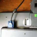
We look at the switch block from the back and see this picture (almost like this, this photo was taken when everything was already fixed, we are interested in the red and black wires, mine was broken off)
(see photo below)
To be honest, I didn’t immediately figure out how the mechanism worked and soldered the broken wire to the fat solder point on the lever.
But after that I didn’t check how the headlight control modes switch. It turned out that the neighbor seemed to be not turned on, the soldered wiring prevented the switch from being turned completely until there was a clear click. Well, soon the signal disappeared again, and I had to climb again.
It turns out that when switching headlight modes, the inner rod to which the wires are connected rotates:

The image has been reduced. Click to see original.

The image has been reduced. Click to see original.

The image has been reduced. Click to see original.
Well, it’s clear - the wires experience cyclic bending loads, the more often you switch the headlights.
Now we disassemble the block to completely replace the wires (I changed both at once, without waiting for the second standard one to break).
Unscrew the two screws on the block cover

The image has been reduced. Click to see original.
Cover - to the side

The image has been reduced. Click to see original.
Carefully pull the lever upwards from the switch housing

The image has been reduced. Click to see original.

The image has been reduced. Click to see original.
Now you need to remove the rotating part from the lever, which actually switches the headlights.
We take a flat-head screwdriver, hold the lever into a fist, and act in the same way as many people open bottles - we rest the screwdriver, like a lever, against the base of the index finger, tighten the rotating part (it is held on the rod due to a tight fit)

The image has been reduced. Click to see original.

The image has been reduced. Click to see original.

The image has been reduced. Click to see original.
I also removed the horn button from the rotating part (it is held on by two latches)

The image has been reduced. Click to see original.
And it turned out that it was not in vain - one contact pad was burnt due to the fact that one contact on the rod was longer than the other. Well, and, of course, due to the fact that there is no relay in the sound signal control circuit, all the current passes through the button (a reason for thought for those who install more powerful signals)

The image has been reduced. Click to see original.
I cleaned the contact pad, did not grind the contact down - I tapped it, which caused it to flatten a little. Well, good - the contact area will be larger.

The image has been reduced. Click to see original.

The image has been reduced. Click to see original.
We pull the rod out of the lever, unsolder the wires from the switch block, unsolder the wires (or their “stubs”) from the rod.
We are looking for wires of suitable diameter, because they must fit into the holes on the rod. If they fit, take pieces of wires of the required length. I took longer ones than the standard ones (in the first photos, where, in fact, everything is already ready, you can see that their stock is clearly larger) in order to reduce the influence of the breaking moment.
We solder and wrap around the rod, placing it in the corresponding grooves and threading it through the corresponding holes.

We will not describe in detail how to remove the steering column cover, we will only tell you that you need a Torx screwdriver, I don’t remember what size and long enough. It turned out to be very difficult to get a screwdriver into the “star” of the screw, because it is located quite deep and at some unnatural angle that you don’t expect and poke somewhere past.
After removing the casing, turn the steering wheel in the “9 o’clock” direction and unscrew the two screws securing the left steering column switch. Disconnect the wire block.
We look at the switch block from the back and see this picture (almost like this, this photo was taken when everything was already fixed, we are interested in the red and black wires, mine was broken off)
To be honest, we didn’t immediately figure out how the mechanism worked and soldered the broken wire to the fat solder point on the lever.
But after that they didn’t check how the headlight control modes were switched. It turned out that the neighbor seemed to be not turned on, the soldered wiring prevented the switch from being turned completely until there was a clear click. Well, soon the signal disappeared again, and I had to climb again.
It turns out that when switching headlight modes, the inner rod to which the wires are connected rotates:


Well, it’s clear - the wires experience cyclic bending loads, the more often you switch the headlights.
Now we disassemble the block to completely replace the wires (we changed both at once, without waiting for the second standard one to break).
Unscrew the two screws on the block cover

Cover - to the side

Carefully pull the lever upwards from the switch housing


Now you need to remove the rotating part from the lever, which actually switches the headlights.
We take a flat-head screwdriver, hold the lever into a fist, and act in the same way as many people open bottles - we rest the screwdriver, like a lever, against the base of the index finger, tighten the rotating part (it is held on the rod due to a tight fit)


We also removed the horn button from the rotating part (which is held on by two latches)

And it turned out that it was not in vain - one contact pad was burnt due to the fact that one contact on the rod was longer than the other. Well, and, of course, due to the fact that there is no relay in the sound signal control circuit, all the current passes through the button (a reason for thought for those who install more powerful signals)

The contact pad was cleaned, the contact was not ground down - they tapped it, which caused it to flatten a little. Well, good - the contact area will be larger.


We pull the rod out of the lever, unsolder the wires from the switch block, unsolder the wires (or their “stubs”) from the rod.
We are looking for wires of suitable diameter, because they must fit into the holes on the rod. If they fit, take pieces of wires of the required length. We took longer ones than the standard ones (in the first photos, where, in fact, everything is already ready, you can see that their stock is clearly larger) in order to reduce the influence of the breaking moment.
We solder and wrap around the rod, placing it in the corresponding grooves and threading it through the corresponding holes.


Further, during assembly, there is only one difficult moment - to put the rotating part back on the rod. How we did it: we inserted the rod into the lever, fitted the rotating part, placed the lever vertically on the table, took a bit screwdriver without the bit itself (you can use a small head or any hollow object of a suitable shape), and used it as a mandrel. Light blows on the screwdriver forced the rotating part into place

Once the rod is installed, you can solder the wires to the contacts on the switch block.
Assembly is carried out in reverse order.
When installing the steering column cover, pay attention to two points:
1. so that the rubber boot on the lever is correctly oriented - it can rotate around the lever. You will understand how to install it correctly in place.
2. so that the screws that were unscrewed at the very beginning get where they should be. This must be done before snapping the top part of the casing into place.
Hello everyone, today I would like to talk about why the signal on a Lada Largus car does not work. Largus has a two-tone sound signal. There is also no signal relay, and both signals are connected when turned on through a fuse. If it suddenly happens that you press the signal, by the way, the button for turning on the sound signal on Largus is located on the steering column switch on the left, and you do not hear a sound, it means that something went wrong and the first thing you need to check is fuse F17 (15A).
If necessary, you need to replace the signal fuse, and if after replacement it burns out again, then you need to look for the location of the short circuit. After checking the fuse, if it turns out to be serviceable, then the cause should be looked for in the steering column switch.
In the steering column switch, the black wire at the base of the soldering tends to break off, and in this case you have two options: buy a new switch, which is not that cheap, or do soldering, provided you know how to do it. Possible malfunctions of the Lada Largus sound signal also include the sound signals themselves. But the likelihood that both will refuse at once is very small.
Well, that’s all we have looked at the main reasons why the sound signal on a Lada Largus car does not work. Bye everyone.
Removing sound signals Lada Largus
We carry out work when replacing sound signals.
Depending on the configuration, the vehicle may be equipped with one or two sound signals. The signals are located behind the front bumper. If there is one signal (high tone), it is located on the right side, if there are two signals, on the right - high tone, on the left - low tone.
Using a 13mm wrench, unscrew the bracket fastening bolt.
We remove the signal with the bracket and disconnect the wire block from the signal connector (see above).
Set the low tone signal in the reverse order.
How to fix a car horn, instructions for use

According to the Russian Federation Traffic Regulations and the list of faults presented therein, it is prohibited to operate a vehicle with a non-functioning sound signal.
An ordinary situation, let's say. Early morning, you are driving your car to work and suddenly, unexpectedly and shamelessly, you are “cut off” by a neighbor in the flow of traffic, wedging into your lane. Your further actions are naturally predictable, you immediately hit the brakes and hit the horn with your palm as hard as you can. But bad luck, instead of a powerful signal escaping from the depths of the car’s hood, there is deathly silence. Of course, you managed to avoid an accident, but you failed to warn the boor or just a sleepy, unwary driver. The morning didn't start out well as you had planned.
Of course, there are options and situations that are much worse, when a non-working sound signal led to truly tragic consequences. An inattentive pedestrian running onto the road, or a cyclist running out onto the road, or worse, any teenager or a very small child... A terrible situation, what is there to hide, which might not have happened if the car’s sound signal were working at that moment.
In this article, dear readers, we will figure out how to fix the signal yourself. Let's get started.
As a rule, the circuit of such a sound signal consists of the following elements: - the signal itself, the switch, the fuse and the relay. Voltage battery supplied through a fuse to the relay winding and to the contacts. When you press the sound signal, the relay is activated and the electrical circuit is closed, and then the sound signal is activated. In some cars vehicles such a relay is not used, which means the voltage is supplied directly through the horn switch directly to the horn. In this article, dear friends, we will look at the possibilities of how you can check and repair each of the components of this simple system yourself.
How to fix a broken horn
1. Purchase the necessary tools. To fix the signal on your car you will need the following: - a digital multimeter or a regular multimeter, protective gloves, a quick-release connection, a repair manual for your car, safety glasses, crimping pliers and wire strippers (can be replaced with a regular knife), and of course spare ones wires.

2. Locate the fuse box. First of all, you need to check whether the fuse or the relay itself has failed. The location of the fuses and their diagram can be found in the user manual. Typically, one fuse box is located in the dashboard on the driver's side and another one is located under the hood of the car.
Advice:-if you don’t have a car manual at hand, you can enter the model and year of manufacture of your car in an online search, and then find circuit diagrams and instructions for fixing the signal on the Internet. There is a high probability that you will find what you are looking for there.

3. Finding the right fuse. Examine the diagram on the back of the fuse box and find the fuse number that matches the horn circuit.
Advice:-this information is duplicated in the manual for your car, in it you can look and find a diagram for each of the fuse blocks.

4. Remove the fuse. Once you have identified the fuse in the circuit you are interested in, pull it out with the special plastic pliers you find in the fuse box. If they are not in their rightful place, then call on your ingenuity to help. But be very careful not to break the connectors.

5. Check the fuse. In order to identify a breakdown, whether the problem is really in the fuse, you will need to check that it is working; perhaps it has simply blown. This can be done in two ways, for example, if a break is visible inside the U-shaped wire, then the fuse itself needs to be replaced, it naturally burned out. If the wiring inside it is intact, this is not a guarantee that everything is in order with the fuse. Thus, we move on to the second stage of verification.

6. Check the fuse using a multimeter. Test the fuse with a multimeter.
When using a digital multimeter, you need to use the device’s adjustment knob to select the position for measuring the minimum resistance value with a sound signal (if your multimeter has such a setting).
When measuring with an analog (arrow) tester, it is necessary to select the starting position for measuring the minimum resistance value in Ohms. Then you need to calibrate the device by connecting the probes to each other and then, using the adjustment knob, move the arrow to the zero position, that is, set it to zero.
We press the probes to the fuse contacts. For a working fuse, the tester should show zero ohms. Conversely, if the needle or DMM readings do not change, the resistance is excessively high, then the fuse has blown.

7. Install a new fuse. If the fuse is broken, install new one the same current rating (10, 20, 25, 30 Amperes, etc.). To do this, simply insert the new fuse back into the appropriate slot.
Note:-Keep in mind that fuses do not blow out for no reason, they fail at the moment and in order to protect the circuit itself from excessive current. Watch the newly installed fuse for a moment. If it burns out again, you will need to check the circuit for faults.

8. Locate the relay box. If the fuse is good, the next part of the test we move on to is the horn relay. The location of this relay can also be found in the owner's manual. Typically, the relays are installed in the fuse box under the hood.

9. Check the relay. The simplest and at the same time effective way check the correct operation of the relay, take and swap the horn relay with another identical relay in the car. As a rule, “relays” of the same design can be used on a couple of other circuits, which, if necessary, allows you to replace them in the machine. If, after replacing the relay, the horn (sound signal) starts working, we can state the fact that the problem was in the relay and it should simply be replaced.
The fault may also lie in the horn switch.

10. Remove the relay and set up the tester. Use your vehicle's repair manual to determine which relay terminal is controlled by the relay switch. Most relay switches are located inside the steering wheel. This will require opening the steering wheel by accessing the two screws on the left and right side of the steering wheel.
Attention:-The horn switch is usually part of the steering wheel. In modern vehicles this means that it is part of the airbag system. Improper maintenance of the airbag system may result in accidental deployment of the airbag and/or damage to the airbag system itself. Thus, friends, remember, if you suspect that the malfunction lies precisely in the horn switch, then it is advisable to leave further repairs to qualified personnel in a car repair shop.

11. Check the horn switch. If the horn switch itself does not receive power, the horn button will no longer respond to pressing.

12. Check the relay switch. Remove the relay and set the position to measure the resistance value in Ohms. Apply one tester probe to the relay switch socket, and the other to the negative terminal of the battery. Have an assistant press the horn button to check the tester readings.
Advice:-You should see numeric values on the screen. A continuous “Out of Limits (OL)” display on the tester means the breaker is not tripping and needs to be replaced.

13. Test the sound signal itself. Standard locations for sound signal devices are usually located behind the false radiator grille, in front of the main radiator.

14. Identify plus and minus. Using your vehicle's repair manual, determine which wire is the positive wire and which is the negative wire that goes to the horn.

15. Checking the sound signal directly from the battery. ABOUT Disconnect the horn connector and place the wire directly between the positive terminal of the battery and the positive terminal of the horn. Do the same operation with the negative terminal from the battery and the negative signal terminal. When touched by the negative wire, a working signal should begin to emit sound. Otherwise, this horn is simply faulty and needs to be replaced. ATTENTION! BEWARE OF SHORTING THE TWO WIRES COMING FROM THE BATTERY TO EACH OTHER!
16. Check the circuit. If the horn still doesn't work after you've tried all the methods we've described above, and you've also replaced all the faulty components, then the last place to look is the horn circuit itself.

17. Check wiring. If you have checked everything, but the beep is still silent, then the problems lie in the electrical circuit itself. Check the circuit grounding, current and voltage parameters in the power supply, as shown below.
18. Check the circuit grounding. IN In accordance with the instructions for your car, determine the grounding of the circuit itself. To test the ground, you need to install a measurement meter in Ohms. Then, touch the negative pin with one tester probe to the horn (-) connector, and touch the ground with the other. If the wiring is working properly, the display should show numeric values.
19. Checking the power supply wire of the circuit. According to your car's manual, identify the power wire. Your device should show battery voltage when tested.
Everything we described in this article is designed for people who are curious and not afraid of difficulties. But in any case, and in principle, you and any motorist-driver will not have any difficulties here, especially if you have basic knowledge of electronics for your car and have already applied this knowledge in practice. For all other motorists-drivers, the most reasonable thing would be to visit a service station (service station), where they will diagnose the car and, if necessary, repair the car’s sound signal. Professional repairmen can save you not only time and money, but will also allow you to avoid such mistakes in the future.
The electrical circuit for connecting a two-tone sound signal on a Lada Largus passenger car is quite simple, since there is no relay for turning it on. It turns out that both signals, when turned on, are connected through the fuse and its power button directly to the battery power source or generator.
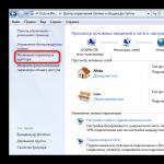
If, when you press the horn button located on the left lever under the steering switch (which is unusual for VAZ cars), not a single sound is heard indicating that the signal did not work, then the driver will have to look for the malfunction in his electrical diagram. First of all, you need to check the condition of fuse F17 (15A), which protects only this electrical circuit, located in the interior mounting block on the left side of the front panel. Its location can be determined by the pictogram printed on the back of the cover covering the mounting block.
Replace the blown fuse F17 with a new one. If, after turning on the sound signal, this fuse fails again, then you will have to look for the location of the short circuit in its electrical circuit. And if fuse F17 turns out to be intact, then most likely you will have to look for a fault in the left under the steering switch, since it is there that the black wire most often breaks off at the base of the solder, as a result of which power to the sound signals stops being supplied.
There are two ways to fix this problem. The first way, which consists in replacing the steering switch, is the most expensive financially, since the prices for it are quite high. The second way is only for those drivers who can normally use a soldering iron and are not afraid to disassemble this one for the steering switch. To do this, you will need to remove the casing covering the steering column, unscrew a couple of screws and remove the switch housing. But, for soldering you will need a soldering iron with a thin tip, since the contact to which the wire needs to be soldered is located in a recess.
Possible malfunctions include the failure of the sound signals themselves, but the likelihood that both will not work at once is quite small. And if one of them refuses to work, then you can get to its location (behind the bumper) by removing the right or left wheel arch protection, depending on which of the sound signals has stopped working.