In many household appliances and industrial automation devices of relatively recent years, mechanical meters are installed. They are products on the conveyor, coils of wire in winding machines, etc. In the event of a failure, it is not easy to find a similar meter, and it is impossible to repair due to the lack of spare parts. The author proposes to replace the mechanical counter with an electronic one.
An electronic counter being developed to replace a mechanical one turns out to be too complicated if it is built on microcircuits of a low and medium degree of integration (for example, the K176, K561 series). especially if a reverse account is needed. And in order to save the result when the power is off, it is necessary to provide a backup battery.
But you can build a counter on just one chip - a universal programmable microcontroller that incorporates a variety of peripheral devices and is capable of solving a very wide range of tasks. Many microcontrollers have a special memory area - EEPROM. The data written to it (including during program execution), such as the current counting result, are retained even after the power is turned off.
The proposed counter uses a microcontroller Attiny2313 from the Almel AVR family. The device implements a reverse counting, displaying the result with blanking of insignificant zeros on a four-digit LED indicator, storing the result in EEPROM when the power is off. The analog comparator built into the microcontroller is used for timely detection of a decrease in the supply voltage. The counter remembers the result of the count when the power is turned off, restoring it when turned on, and, similarly to a mechanical counter, is equipped with a reset button.
The counter scheme is shown in the figure. Six lines of port B (РВ2-РВ7) and five lines of port D (PDO, PD1, PD4-PD6) are used to organize dynamic indication of the counting result on the LED indicator HL1. The collector loads of the phototransistors VT1 and VT2 are resistors built into the microcontroller and included in the software, connecting the corresponding outputs of the microcontroller to its power circuit.
An increase in the result of counting N by one occurs at the moment of interruption of the optical connection between the emitting diode VD1 and the phototransistor VT1, which creates an increasing level difference at the input INT0 of the microcontroller. In this case, the level at the input INT1 must be low, i.e., the phototransistor VT2 must be illuminated by the emitting diode VD2. At the time of the rising edge at the INT1 input, with a low level at the INT0 input, the result will decrease by one. Other combinations of levels and their differences at the inputs INT0 and INT1 do not change the counting result.
When the maximum value of 9999 is reached, the count continues from zero. Subtracting one from the zero value gives the result 9999. If the countdown is not needed, you can exclude the emitting diode VD2 and the phototransistor VT2 from the counter and connect the INT1 input of the microcontroller to a common wire. The account will only go to increase.
As already mentioned, the analog comparator built into the microcontroller serves as a voltage drop detector. It compares the unstabilized voltage at the output of the rectifier (diode bridge VD3) with the stabilized voltage at the output of the integrated regulator DA1. The program cyclically checks the state of the comparator. After the meter is disconnected from the network, the voltage on the filter capacitor of the rectifier C1 drops, and the voltage stabilized remains unchanged for some time. Resistors R2-R4 are selected as follows. that the state of the comparator in this situation is reversed. Having discovered this, the program has time to write the current count result to the EEPROM of the microcontroller even before it stops functioning due to a power off. The next time the program is turned on, it will read the number written in EEPROM and display it on the indicator. The count will continue from this value.
Due to the limited number of pins of the microcontroller, pin 13 was used to connect the SB1 button, which resets the counter, serving as the inverting analog input of the comparator (AIM) and at the same time as the "digital" input of PB1. The voltage divider (resistors R4, R5) here sets the level perceived by the microcontroller as a high logical When you press the SB1 button, it will become low. This will not affect the state of the comparator, since the voltage at the AIN0 input is still higher than at AIN1.
When the SB1 button is pressed, the program displays a minus sign in all digits of the indicator, and after releasing it starts counting from zero. If the counter power is turned off while the button is pressed, the current result will not be written to EEPROM, and the value stored there will remain the same.
The program is designed in such a way that it is easy to adapt to a counter with other indicators (for example, with common cathodes), with a different PCB layout, etc. A slight correction of the program will also be required when using a quartz resonator with a frequency that differs by more than 1 MHz from the one indicated.
At a source voltage of 15 V, the voltage is measured at pins 12 and 13 of the microcontroller panel relative to the common wire (pin 10). The first should be in the range of 4 ... 4.5 V, and the second should be greater than 3.5 V, but less than the first. Then the source voltage is gradually reduced. When it drops to 9 ... 10 V, the difference in voltage values on pins 12 and 13 should become zero, and then change sign.
Now you can install a programmed microcontroller into the panel, connect the transformer and apply mains voltage to it. After 1.5 ... 2 s, you need to press the SB1 button. The counter indicator will display the number 0. If nothing is displayed on the indicator, check the voltage values at the inputs AIN0.AIN1 of the microcontroller again. The first must be greater than the second.


In the last article I shared with you,. The thick wire was wound by hand, since it was not possible to carefully lay the coil to coil in another way at home. With a smaller diameter of the winding wire, a more technologically advanced method can be used, which will reduce the time and effort during winding, and, what is also important, the manufacture of the transformer will not differ from the factory version. Next, a simple design of a home-made winding machine will be described, with which you can easily wind coils, chokes, power and sound transformers.
The base (bed) of the winding machine
You can make a machine for winding transformers from any durable, easily processed material. The most suitable would be: metal, plywood (wood) or plastic. Depending on what you have available and what you like to work with the most, you can give preference to one or another material.
Basically, I make homemade products from what I have at hand, so in this case, in the rubble of junk called “useful on the farm”, there were scraps of 10 mm semi-rigid plastic, which I successfully used in the design of the winder and its elements.
Initially, during development, it is necessary to make a trial layout, think over the layout of the winder, ask yourself what necessary functions the device should perform. In the process of prototyping, it is easy to supplement and improve, adjust the dimensions, which will allow you to get the most successful version at the end.
According to the project, we have three axes:
The first axis (winder) - the winding coil of the transformer will rotate on it. At one end, a counter for the number of turns made will be attached, and at the other end, an axis rotation drive with a set of pulleys. The drive can be manual in the form of a fixed handle on the axis or electric in the form of a stepper motor.
The second axle (stacker) - the leash of the wire layer will “run” on it, the second set of pulleys will also be fixed on the axle, which will be mated with the first set of pulleys on the first axle through a belt drive using a belt.
The third axis (reel holder) serves as a support for the coil with winding wire.
At the design stage, the axes should be correctly spaced apart so that the frame of the wound coil of the transformer does not cling to the machine and does not touch another axis, and also choose the height of the wire coil so that coils of different sizes can be freely hung. It is possible to provide an additional axis for winding-winding wire from coil to coil.
According to the marking on the selected material for the bed with a hacksaw, we cut out parts of the base of the machine (sidewalls, bottom, crossbars), we also drill the necessary holes. Using metal corners and self-tapping screws, we fasten all the components together.


Revolution counter for counting turns
One turn is equal to one turn - this is how I used to count in my mind, winding the transformer on a primitive device. With the advent of a full-fledged winding machine with a provided counter, it became much easier, but most importantly, when winding the turns, the percentage of error was reduced to almost zero.

In the winder under consideration, a UGN-1 (SO-35) mechanical counter from Soviet equipment was used. It can be replaced with a bicycle counter or a mechanical counter from an old household tape recorder, where it measured the consumption of the tape. You can also assemble a simple counter with your own hands, having only a calculator, a reed switch, two wires and a magnet.
Disassemble the calculator into two contacts, closed by the "equal" button, solder two wires, and solder the reed switch to the ends of the wires. If you bring the magnet to the reed switch, then its plates inside the glass bulb will close and the calculator will simulate pressing a button. Using the calculator's 1+1 addition function, you can calculate the revolutions.


Next, we fix the homemade disk on the first axis. We glue a magnet to the disk, and we attach a reed switch to the machine body or bracket. We position the reed switch in such a way that when the disk rotates, the magnet passes next to the reed switch and closes its contacts.
According to this principle, it is possible to replace the reed switch with a limit switch, and make the disk in the form of an eccentric. The eccentric disk, rotating with its convex part, will press the limit switch
Coil stacker
The wire stacker is used for uniform winding, turn to turn, of the winding wire on the frame of the transformer or coil being manufactured. The winding density depends on the speed at which the axles rotate, as well as on the diameter of the selected wire. The required ratio of the speed of rotation of the first and second axles can be achieved using pulleys and a belt drive. During the operation of the debugged mechanism of the machine, the stacker roller moves simultaneously with a certain step and the wire is laid on the frame of the wound transformer. In a nutshell, it’s impossible to explain, but upon further reading of the article, everything will become clear.
In the design under consideration, a factory-made M6 stud-rod with a thread pitch of 1 mm was used. Bearings are fixed parallel to each other into the holes drilled for them in the sidewalls of the winding machine bed, then a pin is inserted into them. Lubricate the bearings for the best glide. A guide roller moves on the hairpin, through which the wire is threaded.


The guide roller for laying the wire can be made independently, having a small piece of U-shaped aluminum profile, an elongated sleeve nut corresponding to the thread of the stud, and a feed roller with a groove in the middle.

In the U-shaped profile, holes are drilled parallel to each other. The upper pair of holes is for the roller, and the lower pair is for the elongated nut. The diameter of the upper holes in the walls of the profile is selected along the axis on which the roller will be fixed, and the lower ones are one millimeter larger than the thread diameter of the stud. Under the distance between the walls of the profile, an elongated nut is fitted tightly in size. Then this design is screwed onto the stacker stud.


The stud is fixed with nuts on the sides so that it can rotate without displacement. On one side, a stock of stud is left in order to wind pulleys on it to mate the first and second axles.
Two pulleys connected by a belt drive
The axes in the winding machine are interconnected by a system of pulleys of various radii. The pulleys fixed on the axles are rotated by means of a belt drive. A belt is used as a belt.
— Stacker axle pulley is 100mm;
- The pulley on the axis with a fixed coil (winder) is equal to the thickness of the required wire multiplied by 100.
For example, for 0.1 mm wire, a 10 mm pulley on the winder axle is applicable. For diameter 0.25 wire 25 mm pulley.
If possible, it is better to make pulleys with a pitch of 1 mm and select during the winding process using this formula
The error depends on the accuracy of the diameter of the manufactured pulleys and the belt tension. If a stepper motor with a gear transmission is used in the design as a drive instead of a belt and precisely sawn pulleys, then the error can be brought closer to zero.
Now I’ll tell you how to make a pulley with your own hands at home without turning to a turner. My set of pulleys is made of the same material as the bed of the winder. I marked out the required diameters of the pulleys with a compass and added a few millimeters to the large side in order to machine the groove for the belt to the desired size. Holes were drilled along the marking contour with a screwdriver and partitions were cut between them. So I scored the required number of blanks for pulleys. In the role of a lathe, I had an unnecessary meat grinder "Helper" adapted.


I don’t remember exactly whether I cut a thread on the shaft of the meat grinder motor or it turned out to be suitable there, but a stud was screwed through a long sleeve nut. A workpiece of a slightly larger diameter than the required pulley was screwed onto the stud through nuts and washers. The meat grinder was turned on and with a hacksaw for metal / a file all the irregularities were rounded to a round shape, and a groove (groove) for the belt was machined with a needle file. In the process, the diameters of homemade pulleys were periodically checked with a caliper.


Components of the winding machine and the principle of its operation
The elements of the winding machine were assembled slowly. Almost everything was taken from old Soviet film equipment. Moving parts: handle, axle studs, guide roller - all equipped with bearings. The studs, nuts, washers and angles were purchased from a hardware store. I had to spend money only on studs, long nuts and corners. Otherwise, everything is made from improvised materials available.

For precise selection of wire winding density, a set of several pulleys is strung on the stud of the stacker. So, in the case of not tight winding, it was possible to transfer the belt by one size and adjust the speed of rotation of the axes. The belt in the process of winding the wire is twisted, depending on the direction of the winding stroke, according to the type of “Eight” shape or the direct position of the belt. A couple of dozen trial turns should be made in order to correctly fit the pulleys to the wire diameter.


The base is made of wood or other material according to the shape of the inside of the transformer coil and is fixed on the stud with wing nuts. You can also make universal holding corners to fix the coil. A demonstration of the winding machine is shown in the video:
[Here will be a video of the transformer winding process]


![]()
About the author:
Greetings, dear readers! My name is Maxim. I am convinced that almost everything can be done at home with your own hands, I am sure that everyone can do it! In my free time, I like to craft and create something new for myself and my loved ones. You will learn about this and much more in my articles!
I have long wanted to assemble a coil counter for a manual winding machine. I wanted to make a battery-powered device from two microfinger batteries, consuming little energy in the operating mode, having a simple push-button control - “Reset”, “On / Off”. The counter must be able to count backwards. Sometimes you have to unwind the coils, or there are non-standard situations.
STM8S003F3P6 and STM8L051F3P6 were available in TSSOP-20 packages. It turned out that S003 is not suitable for my idea - it has a 3-5V power supply, and most likely the microcontroller will not work with a 50% discharge of a 3V battery. Therefore, the choice fell on STM8L051F3P6. According to the datasheet, it has power from 1.8 to 3.6v. As a display, it was decided to use the MT-10T7 of the Russian manufacturer MELT. This LCD was bought about 7 years ago, since then I have not found a worthy application. It was a pity to throw it away.
Let's talk about the sensor. First, I used integral Hall sensors that form a logic signal at the output. We got it from the board of the underwater lamp. It turned out that they stop working even at a small number of revolutions. This upset me. I had to reinvent my wheel. I decided to use hall sensors from the cd-rom drive motor and lm358 op-amp. It was highly doubtful that this idea was working from the 3rd century. But the attempt is not torture. To my surprise, the circuit worked perfectly with such nutrition.

The scheme couldn't be easier. R5-sets the current through the Hall sensors U1,U2. On DA1, an amplifier with KU = 50 was made. The signals from the outputs of DA1 do not correspond to the logic levels of STM8, therefore, transistors Q1, Q2, representing the level converter, are connected to its outputs. Why the board provides elements C1, C2, I don’t even remember. Obviously I was going to deal with interference. The transistors are actually bc817-40. But those in the diagram should work. Hall sensors hw-101A (marking D).
Power for the sensor and the display come from the PB1 pin of the microcontroller. Load capacity for these purposes is more than enough.

R1 is a jumper. I didn’t find a nominal value of 0 Ohm, so I put the smallest one that was.
The maximum value for the account is 65535. The "RESET" button is used to reset the counter, "ON / OFF" - on / off the device.
The printed circuit board can be called rather debugging.


Photo of the finished device.
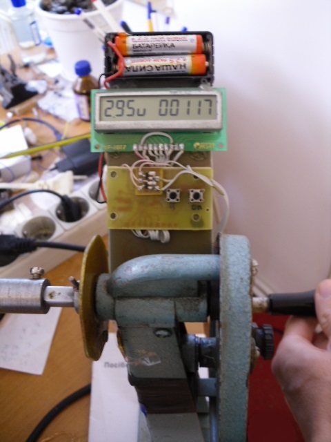
A fiberglass disk acts as a speed sensor, with a niodium magnet glued on it with a diameter of 5 mm, a thickness of 1 mm, and a board with Hall sensors. The distance between the magnet and the sensors is about 5 mm. Half of the familiarity on the display remained unused. I didn’t come up with anything smarter, how to show the supply voltage there. The contrast of the indicator is not enough, so I had to tilt the entire board at 45 degrees. In the photo, the sensor is attached with adhesive tape, then I attached it with several turns of electrical tape. The design turned out not very aesthetic, but that's enough for me. The winder itself is nothing more than an old mechanism for rewinding film. I don’t know what manipulations it was intended to perform, but a reel of film is put on it. The indicator, battery compartment, microcontroller board are glued to a piece of textolite with hot glue.
Current consumption in the on state 12.8 mA, in the off state 1.71 μA.
Software.
The code is written in the IAR Embedded Workbench IDE. The microcontroller is powered by a built-in HSI RC generator with a frequency of 16 MHz. The TIM2 general-purpose timer is responsible for counting the number of turns. It has a 16-bit counting register, and the ability to work with an encoder (encoder mode). This greatly simplifies the task. Just set a timer and forget it. It will count the values by itself, and implements the possibility of a reverse count. True, due to the peculiarities of this mode, the values in the counter register are twice the real ones.
Of course, the values from TIM2 need to be somehow extracted and displayed on the screen. This is done by the 8-bit TIM4, which generates interrupts, on which this operation takes place. Interrupts come every 8ms. The polling of the "reset" button and manipulations for displaying information from the ADC and TIM2 on the screen have been added to the handler.
The ADC measures the battery voltage. The reference voltage input is internally connected to the positive power supply of the microcontroller. You cannot select an internal source (as is done for example in the AVR). But you can measure the voltage of this very source. The VREF source voltage is measured at the factory and written to the VREFINT_Factory_CONV byte, it can be read.
So that the main program is not bored, it looks to see if the ADC conversion is completed and, based on 16 samples, calculates the average.
Turning the circuit on/off is implemented on the basis of an external interrupt at the push of a button. Upon the arrival of the interrupt, we change the variable, and we sit and wait until the button is released.
If the user wants to turn off the device, then the main program stores the value of the TIM2 counting register in RAM. Makes all unused pins outputs, sets them to zero. If this is not done, I get interference. We turn off the reference voltage source VREF and the ADC and fall asleep. The most economical halt mode is used. The microcontroller will wake up by pressing the "On" button, by external interrupts.
microcontroller firmware.
This is a different story. When I bought STM32F0 Discovery, I thought that the programmer on it can sew STM8. It turned out that it was not. I didn’t want to spend money on a separate programmer, but I wasn’t impressed with the USART firmware capabilities (and not all 8-bit families can do this).
And I didn’t think about anything until some uncomplicated counting device caught my eye. The fact that it should be adapted to count the number of turns of wire wound on the coils of transformers was not in doubt, because there is no higher pleasure than doing one thing while thinking about another. But is it being in a state of complete concentration (akin to trance) and at the same time tambourine counting turns, is this possible? And it's not hard to adapt. As well as finding the same thing or something similar. There are a lot of different meters now, and even a faulty one will do. Moreover, at the beginning you need to carefully, remembering the relative position of the parts (or better to photograph it all), “gut” and throw out everything superfluous.
So, from the internal contents we leave digital wheels, gears, axles for their landing and rack-axle holders that we assemble “in place” (as they stood before disassembly). It is advisable to glue the axles into the left rack. On digital wheels, next to the central hole there is another one - an assembly hole, with which the wheel is put on a hairpin (a smooth and elastic wire that is removed before installing the cap). Nothing will come of it without this helper. At the same time, before attaching the second rack, do not forget to put a rubber belt (preferably flat) of a suitable length on the drive wheel.

In the bottom part and in the cap, in the center, we make through holes (for example, 3 mm in diameter) for their further fastening with a screw and nut. This is mandatory, because during the operation there will be structural shaking, in which everything assembled by us will constantly fall apart (checked). Also, a cut is made in the cap with a width slightly less (so that the belt does not fly off) of the leading digital wheel and a length through the entire cap. One more thing will not be superfluous - two holes in the side wall of the cap, they will come in handy when installing it in place, because in this case you need to get the upper slots on the racks into the corresponding grooves (by the way, the left and right are different in size - do not confuse) inside the cap. Here through them with a screwdriver and direct. In the bottom part, a pair of holes must be provided for fastening the entire, already assembled structure to the winding device with screws or screws.

How and in what place to attach the assembled counter to the winding device - complete freedom of creativity. And here is their working connection - like this:

A pulley (this is ideal) or a soft plastic sleeve with an inner diameter of slightly less than 6 mm (to be pulled tight) and an outer diameter at which one turn of the drive shaft will correspond to one turn of the leading digital wheel of the counter is installed on the drive shaft of the winding device. The simplest option is to wrap a narrow adhesive tape with a sufficient thickness (say, up to a diameter of 20 mm) on a suitable PVC or thick plastic tube 10 mm long (say, up to a diameter of 20 mm) and start tuning, if necessary, unwinding or winding the adhesive tape to the optimum thickness.

In short, we achieve the ratio of the gear ratio One to one. Especially without persisting, it turned out to make an error of +1 turn per 150 revolutions of the winder shaft. Well, the known error completely excludes the unsatisfactory result of the work. Now, while working, you can dream, sing songs and, if necessary, adequately reflect the attacks of other family members. Wishing you success, Babay.
Discuss the article COUNTER COUNTER
For all radio amateurs, or enthusiasts who are fond of sound-reproducing equipment, the winding machine is an extremely popular piece of equipment. Such devices are used for winding single-layer and multi-layer coils of cylindrical type for transformers.
In this article, we will study the device and the principle of operation of the winding machine, and also consider step-by-step instructions, following which you can make such equipment with your own hands.
1 Design and principle of operation
The winding machine is indispensable in the production of the same type of products. There are two types of such units - automatic and manual, while the latter are practically not common in the industrial sector due to limited functionality.
However, the overall dimensions, heavy weight and cost of automatic winders make them inapplicable in everyday life, so it is better to get a manual machine for the home. The standard design of such a device consists of the following elements:
- a supporting frame of two vertical racks made of metal or wood, between which horizontal axes are fixed (on the central rack - for plates with a wheel, on the outer one - for the coil itself);
- large and small gears that transmit torque to the coil;
- a handle fixed on a large gear, through which the axis with the coil rotates;
- fasteners - screws and nuts.
![]()
The principle of operation of such a device is extremely simple - the rotation of the handle leads to the winding of a wire or cable on a rotating frame, the stacker guide, which moves the wire in a horizontal plane, is responsible for the uniformity of winding.
The control of the number of turns can be performed both visually and with the help of special counters, the simplest of which is a conventional bicycle odometer. In more advanced machines, a special magnetic reed sensor is used as a counter.
1.1 Store machines
Among industrial winding units, the SRN-05M3 cable winding machine is very popular. This model was put into operation back in the days of the USSR, and since then has proven itself well due to its high reliability and performance. In the secondary market, SRN-05M3 can be found for 15-20 thousand rubles.

SRN-05M3 is made in a cast iron body, the weight of the equipment is 80 kg, the dimensions are 877*840*142 cm. The minimum cable diameter is 0.05 mm, the maximum is 0.5 mm. The unit is equipped with a single-phase electric motor of the UL-62 type, the power of which is 0.18 kW. The highest rotation speed during winding is 5100 rpm.

For household use, the NZ-1 manual machine (China) would be the best choice. Despite the country of origin, NZ-1 is quite reliable and functional equipment. The unit is designed for winding coils with a diameter of up to 150 mm, with a maximum width of not more than 100 mm. The gear ratio is 1:08 in fast winding mode and 1:0.1 in slow winding mode. The maximum speed is no more than 1000 rpm.
The NZ-1 is equipped with a mechanical type counter. The body is made of metal, the base frame is made of cast iron. The machine is equipped with a pulley, which allows you to connect an electric motor to it through a belt drive and work in automatic mode. The cost of such equipment varies between 4-5 thousand rubles.
1.2 Homemade winding machine (video)
2 We make a do-it-yourself winding machine
The cable winding machine presented in this section of the article allows you to work with coils on a square, round and rectangular frame with a diagonal of up to 200 mm, it can be equipped with different pulleys, which will allow you to change the winding pitch within 0.3-3.2 mm.

The above diagram shows the frame of the machine. To assemble the bed, metal sheets with a thickness of 15 mm (for the base) and 5 mm (for the side sections) are used. Savings on the thickness of the metal is not welcome, as it leads to a decrease in the weight of the unit and, as a result, a deterioration in its stability.
You will need to cut out the frame blanks (dimensions are observed) and drill two through holes in them, then the sides are welded to the base plate. In the lower hole you need to mount 2 bearings, in the upper hole - bushings for the rotation shaft.

As a shaft, you can use a bar of smooth reinforcement 12 mm, which must first be sanded and painted. For the stacker sleeve, you can take a bar with a diameter of 10 mm, along the entire length of which a thread of the M12 * 1.0 standard is cut.

Pulleys are best machined triple, but keep in mind that their total thickness should not exceed 20 mm. With a greater thickness, it will be necessary to additionally increase the length of the shafts by the same size. The combination of pulleys indicated in the diagram allows the use of 54 different winding steps. If you need to work with wires less than 0.31mm in diameter, you will need an additional 12/16/20mm pulley, with which you can wind 0.15mm wires.

To build a manual drive, you will need a large gear and handle, which are fixed by means of a collet clamp on the upper shaft. Thanks to the use of a collet, you can, if necessary, interrupt the winding and fix the handle, thereby preventing the coil from unwinding.
The coil counter for the winding machine is made from a conventional calculator. You will also need a magnet with a reed sensor (you can buy it at any radio engineering store), the conclusions of which must be connected to the calculator's contacts on the "=" button.
2.1 How to work on a homemade machine?
And so, the equipment is ready, how to work on it? To install the frame for winding, it is necessary to extend the upper shaft from the seat to a length equal to the length of the frame. Next, the right disk and the mandrel of the coil are mounted on the shaft, on top of which the coil itself is put on. At the next stage, the left disk is installed and the nut is screwed on, after which everything is installed in its original position.

A stud is placed in the hole on the upper shaft and the frame is centered, after which the frame is clamped with a nut. Further operations are performed in the following sequence:
- A pulley of a suitable diameter is placed on the supply shaft.
- By rotating the pulley, the stacker moves to the extreme position, to one side of the reel.
- A belt of wire is put on the pulley - a ring or a figure eight. The end of the wire must be passed under the middle shaft, placed in the chute of the stacker and fixed on the frame. The tension of the wire is adjusted by means of clamps on the stacker.
- At the beginning of winding, the combination “1 + 1” is typed on the calculator, after which the handle is rotated. With each complete revolution of the shaft, the calculator will independently increase the number on the screen by one, thereby counting the number of turns of wire.
Since this equipment has an extremely simple device, which does not have any controller for controlling the winding machine, during operation you will need to constantly monitor the coil and, if necessary, correct the cable on the frame manually.

If you want to make the machine more functional, you will need to complicate the design by adding a controller to it. This will automate the workflow, however, for fully mechanical pairing, a stepper motor must be installed on the controller (a regular 24-volt drive operating in 44-60 steps per revolution will do). Power transistors for this kit are selected based on the characteristics of the motor. As a controller, the ATmega8 device is optimal, which you can buy for 150-200 rubles.